Creating Movements
Each scene has a series of objects that can be transformed; they can be Xsheet columns (or Timeline layers), pegbars, cameras, or the table.
Every transformation you set for an object at a specific frame automatically defines a keyframe. When keyframes are defined at several frames, in-between positions are automatically interpolated.
To create more complex animations, you can also work in a 3D environment, where cameras and scene elements can be placed like on a stage at different distances one from another.
Using the Stage Schematic
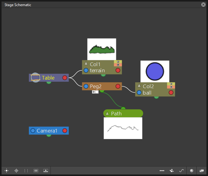
The Stage Schematic contains nodes for all of the objects used in a scene, making it possible to manage the way they are linked to each other. It’s organized in a hierarchy starting from the animation table, where all the columns/layers and pegbars are placed. A camera is available as well, and additional cameras can be defined.
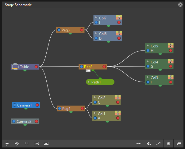
By default the Stage Schematic contains the table node and one camera node.
Column/layer nodes are added as soon as you load or create some content; pegbars and cameras can be added at any time (pegbars will be automatically linked to the table).
When more than one camera is created, you can set which is the active one, used in the Viewer; the active camera node is displayed in blue while the others are left idle in grey. Each camera can have a different size and resolution, and each of them can be animated independently (see Defining Camera Settings ).
Objects nodes can be easily added and arranged and they can be selected in order to be cut, copied, pasted or deleted. When selected, nodes’ edges are highlighted in white; the current node has its label displayed in yellow; when at least one node is selected, its related links are displayed in cyan.
It’s also possible to group several nodes into one single node, in order to better manage a complex Stage Schematic. Groups can be opened to be examined, and its components can be selected for further operations, like creating animations or new groups.
Note
Column/layer nodes have buttons defining their visibility in Camera stand ( ) and Render (
 ) views, these buttons are located at the top right of the nodes: the toggles are linked to the ones available in the Xsheet columns (Timeline layers) headers (see Working with Xsheet Columns ).
Tip
To access the stage schematic:
- Go to the Window menu, and choose the Schematic option.
- If necessary, click the FX/Stage toggle button (
 ) in the bottom bar of the Schematic pane until the title bar displays Stage Schematic.
Tip
To navigate the stage schematic:
Do one of the following:
- Use the mouse wheel, or the zoom shortcut keys (by default + and - keys) to zoom in and zoom out.
- Middle-click and drag to scroll in any direction.
- Use the Fit to Window button (
 ) in the bottom bar of the stage window to display all the objects in the current window.
 - Use the Focus on Current button (
 ) in the bottom bar of the stage window to center the stage on the current object.
 - Use the Reorder Nodes button (
 ) in the bottom bar of the stage window to change the position of the nodes in the schematic to a default arrangement.
 - Use the Reset Size button (
 ) in the bottom bar of the stage window, or use the reset view shortcut (by default the 0 key) to display all the objects at the default size.
Tip
To add a column/layer:
Load or create some content for the Xsheet column (Timeline layer): it will be automatically displayed in the Stage Schematic.
Tip
To add a pegbar:
Do one of the following:
- Click the New Pegbar button (
 ) in the bottom bar of the Stage Schematic window.
 - Right-click in the Stage Schematic and choose New Pegbar from the menu that opens.
Tip
To add a camera:
Do one of the following:
- Click the New Camera button (
 ) in the bottom bar of the Stage Schematic window.
 - Right-click in the Stage Schematic and choose New Camera from the menu that opens.
Tip
To set the active camera:
In the Stage Schematic right-click the camera node you want to set as active and choose Activate from the menu that opens.
Tip
To rename an object:
Ctrl + double-click the node name and type a new one.
Tip
To minimize or maximize column/layer nodes:
Do one of the following:
- Click the arrowhead button to the left of the node name to minimize/maximize it selectively.
- Click the Maximize Nodes (
 ) button in the bottom bar of the Stage Schematic pane to minimize/maximize all of the nodes.
Tip
To select objects and links:
Do one of the following:
- Click to select an object.
- Click and drag to select a group of objects.
- Ctrl-click (PC) or Cmd-click (Mac) to add an object to, or remove it from the selection.
Note
Links can be selected together with objects (see Linking Objects ).
Tip
To move the selection:
Click and drag any object of the selection.
Tip
To edit an objects selection:
Do one of the following:
- Use the Copy command to keep the selection in memory for further operations.
- Use the Cut command to eliminate the nodes selection from the Stage Schematic and keep them in memory for further operations.
- Use the Paste command to paste the selection kept in memory in the Stage Schematic: the pasted selection will be linked to the same object to which the copied or cut objects were linked.
- Use the Delete command to delete the selection.
Note
All of these commands are available in the menu that opens when right-clicking nodes and links.
Note
The table and the default camera cannot be removed from the Stage Schematic.
Tip
To Group selected objects:
Right-click any selected nodes and choose Group from the menu that opens.
Note
Nodes can only be grouped if they share the parent node, and the parent node is included in the selection.
Tip
To open a Group:
Right-click the group and choose Open Group from the menu that opens: the group objects are displayed in a box, showing links between group nodes, and links with nodes outside of the group.
Note
In the Stage Schematic, when the content of a group is displayed it’s not possible to edit the links between group nodes, and links with nodes outside of the group.
Tip
To close a Group:
Click the Close button on the right of the group box bar.
Tip
To release a Group:
Right-click the group and choose Ungroup from the menu that opens.
Tip
To reorder nodes in the Stage Schematic:
Click the Reorder Nodes button () in the bottom bar of the stage window.
Linking Objects
Objects can be linked in order to create shared movements (movements that all the linked objects share with the parent object) and relative movements (movements that are the sum of the object’s own movement and the movement of its parent object).
As parent objects can be linked, in their turn, to other moving objects, it is possible to define a complex hierarchy of transformations.
The hierarchy between objects can be edited by setting links that allow you to set parent and linked objects: columns/layers can be linked to other columns/layers, pegbars, the table or cameras; pegbars can be linked to other pegbars, the table or cameras; cameras can be linked to any object in order to create complex shots, for example with a camera following the movement of a character in the scene.
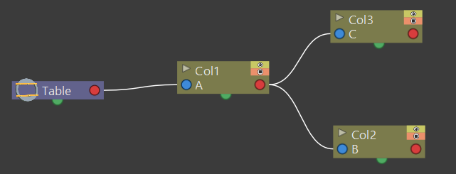
Links can be set by using the ports located at each side of the object node:
- The port on the left is for linking the object to a parent object.
- The port on the right is for linking the object to a child object.
- The port at the bottom is for assigning the object a motion path to follow (see for Creating a Movement along a Motion Path ).
Links can also be selected in order to be deleted: when selected, links are highlighted; when at least one object is selected, the related links are displayed in blue.
Columns/layers and pegbars are always linked, at least to the table: this means that their links cannot be deleted, but only replaced with different ones or restored to their default: the table.
Tip
To link a node to another:
In the Stage Schematic, click and drag from a node’s left port to the parent node’s right port, or viceversa.
Tip
To link a column/layer to another object:
Do any of the following:
- Define the link in the Stage Schematic.
- Select the Animate tool (
 ) with the Pick: option set to Column, and in the viewer Shift-click the column contents to which you want to link the current column.
Tip
To select the linked object to edit in the hierarchy:
Do one of the following:
- Select it in the Stage Schematic.
- Use the Animate tool () with the Pick: option set to Pegbar to click a drawing in the viewer and select the first pegbar in the hierarchy the column containing the drawing is linked to.
- Right-click a drawing in the viewer to choose from the menu that opens the Select command related to the object that you want to edit.
Tip
To select links:
Do one of the following:
- Click to select a link.
- Click and drag to select several links.
- Ctrl-click (PC) or Cmd-click (Mac) to add a link to, or remove it from the selection.
Note
Objects can be selected together with links (see Using the Stage Schematic ).
Tip
To remove selected links:
Choose Edit → Delete, links will be replaced by default ones (i.e to the table).
Advanced Linking
Optionally, the connector ports can be displayed as letters (instead of the default circles), to be able to control, in more advanced ways, the position of the centers to be used when linking the nodes:
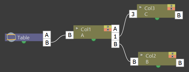
- Center B is the geometrical center of each object (and the default connection option).
- Center A is placed 8 inches to the left.
- Center C is placed 8 inches to the right.
- etc.
When a link is created, the letters at its ends set the way the linked object overlaps with the parent object. If at both ends of the link you set the same letter, the two objects will overlap with no offset respect to their default centers; while if for example, a column centered on B is linked to a pegbar centered on A, it will have an offset of 8 inches to the left.
Apart from letters, columns have also numbered centers as well; these serve for setting links relative to the position of Hooks assigned to these columns (see Using Hooks ).
- Center 1 is the center defined by hook number 1.
- Center 2 is the center defined by hook number 2.
- etc.
Note
While in this mode, each node will have always a free connector port available in order to accept a link to a different center. In this way if you want to link another object to the same parent object, you can choose whether to use the same center or a different one.
Note
By defining parent and child objects you can also create cutout animation (see Creating Cutout Animation ).
Tip
To switch the connector ports display mode:
- Click the Switch Output Port Display Mode button (
 ) in the bottom bar of the Stage Schematic pane until you see the letters on each side of the nodes, instead of the default circles.
Tip
To set the center of an object:
- Place the mouse pointer over the object left port and wait for the double-arrow button to appear.
- Click and drag up or down the double-arrow button to scroll the options available: letters and numbers for columns, and letters for all the other types of objects.
Tip
To set the way a child object overlaps its parent object:
Do any of the following:
- Set the same letter for the two ports at the end of a link to overlap the objects without an offset.
- Set the following letter in alphabetical order on the left port of the child object to offset it to the left: for each successive letter there is an offset of 8 inches to the left.
- Set the following letter in alphabetical order on the right port of the parent object to offset it to the right: for each successive letter there is an offset of 8 inches to the right.
Using Hooks
Hooks are reference points that can be defined for any animation level directly in the viewer, by using the Hook tool ( ).
).
Once defined for a column/layer, they can be used in the Stage Schematic to link another object to it in relation to a specific hook, or to move it, according to any of its hook sets.
In the first case the hook is used as a tracking point to link another object (a column/layer or camera) to a specific feature of the animation level. For example, if you have a character carrying a lamp, you can track the lamp position with a hook, and link a radial gradient to it (placed over the lamp for every frame of the animation) to create a glow.
In the second case, the hook is used as the center of the column/layer where the hooked level will be exposed, thus creating a different center and offset for each level frame. For example, if you have a walking animation cycle, you can set a new center following the character’s feet with a hook, and make the level move accordingly to prevent a moon-walking effect on the background.
Hooks can also be split and passed from one drawing feature to another, automatically creating an offset position. For example, the hook following the character’s foot feature can pass from one foot to another, in order to make the character move continuously onward.
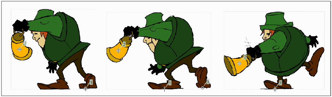
The hook set 2 follows the lamp, while the hook set 1 follows the character’s feet, passing from one feet to another when both are on the ground.
A hook can be created starting from any frame. Once it is created, it will appear on the following level frames in the same position, from where it can be moved.
You can use up to 20 hooks for each level; each hook is labeled with a number, to reference it in each level frame.
By activating the Snap option, hooks for the current level can be accurately placed by snapping them exactly to the same position of hooks defined for the other animation levels visible in the viewer. In case the current level is a Toonz Vector level, hooks will snap also to the center of any closed shapes it may contain (e.g. rectangles, circles or single vector shapes closed with the Tape tool). This option may prove useful especially when defining hooks for cutout animation models (see Creating Cutout Animation ).
Hook information is saved along with each level, as a file in XML format, named as the file but with the _hooks suffix. For example, hooks defined for the level mouse will be saved in the file mouse_hooks.xml .
Note
Hooks are also visible in Onion Skin mode (see Using Onion Skin ).
Note
Hooks can be also used to create a cutout animation model, as they allow you to link the model sections according to specific pivot points (see Creating Cutout Animation ).
Tip
To define a hook for a level:
- Select a frame from the level you want to set hooks for.
- Choose the Hook tool ().
- Do one of the following:
- Click to create a hook and drag to define the hook starting position.
- Click elsewhere to create another hook and the related hook starting position.
Tip
To select hooks:
Do one of the following:
- Click a hook to select it.
- Ctrl-click (PC) or Cmd-click (Mac) to add a hook to, or remove it from the selection.
Tip
To move selected hooks:
Do one of the following:
- Drag them to a new position.
- Shift-drag to constrain an horizontal or vertical movement.
- Activate the Snap option to place the hook exactly at the same position of hooks defined for other animation levels visible in the viewer, or in case the level is a Toonz Vector level, also at the center of closed shapes.
Tip
To pass a hook from one position to another:
- Alt-click and drag the hook to split it into two.
- Place the double circle where the hook has to be for the current frame.
- Place the cross where you want the reference point to be from the next frame onwards.
Tip
To delete a hook:
Select the related hook in any frame and choose Edit → Delete.
Tip
To link an object to a level hook:
- Link the object to the column containing the hook.
- Place the mouse pointer over the column right port and wait for the double-arrow button to appear.
- Click and drag up the double-arrow button to scroll the numbers available before letter A, and release the mouse button to define the hook number to be used.
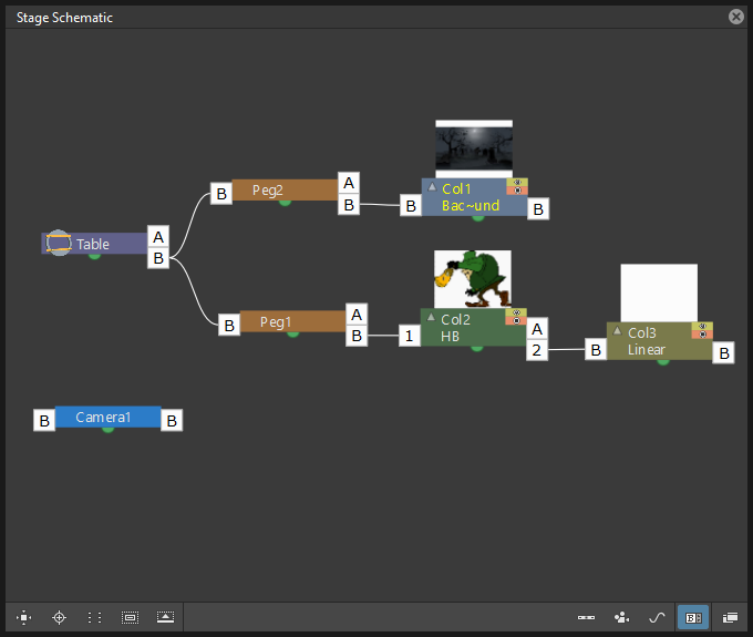
Column 3 is linked to the hook set 2 of column 2, while column 2 is moving according to its own hook set 1.
Tip
To make the level move according to one of its hooks:
- Place the mouse pointer over the left port of the column containing the hook, and wait for the double-arrow button to appear.
- Click and drag up the double-arrow button to scroll the numbers available before letter A, and release the mouse button to define the hook to be used.
Tip
To prevent an animation walking cycle from moon-walking:
Define a hook by following these guidelines:
- Place the hook on the same foot feature along the whole sequence, for example the tip of the foot.
- If the character is supposed to be moving horizontally on the ground, the hook should always lie on the ground line (without changing its vertical position along the sequence). If the feature you are following leaves the ground, still place the hook on the ground line, under the feature you were following.
- When both feet are on the ground line you can split the hook to pass it form one foot to the other.
- If the animation is a cycle and you want the character to keep on walking, the last hook position has to be connected to the first one, and the hook has to pass from one foot to the other by splitting it, and then to the first one again by splitting it again.
Tracking Points
It is possible to automatically track specific regions in a sequence of images by using the Tracker tool (![]() ). The results of the tool are a series of hooks that can be used to link an object to another (see above).
). The results of the tool are a series of hooks that can be used to link an object to another (see above).
![]()
When selected, the Tracker tool (![]() ) allows you to define one or several regions in an image, by defining a center and a size; regions can also be connected to one another to better track points having a visual geometrical relationship. The region defined with the tool sets both, the pattern that the tracking system will try to recognize in the following images, and the size of the search area where it will look for it (that will be of approximately twice that region).
) allows you to define one or several regions in an image, by defining a center and a size; regions can also be connected to one another to better track points having a visual geometrical relationship. The region defined with the tool sets both, the pattern that the tracking system will try to recognize in the following images, and the size of the search area where it will look for it (that will be of approximately twice that region).
Once areas to be tracked are defined in the first frame of a range, it’s possible to automatically track the regions in a selected range, by specifying the following options:
![]()
- Threshold sets the amount of difference between the defined pattern and the recognized one. When using low values, the tracking system will look for an area with an almost identical pattern, and when using high values, will look for an area that can be quite different from the original one. This means that if the value is too low, it’s more likely for the tracking to fail on certain images; if too high, the tracking may fail by following the wrong areas.
- Sensitivity sets how often the defined pattern has to be updated according to the variation it may have in the following images. For the maximum value, the pattern will be updated after each image is tracked.
- Variable Region Size, when activated, will look for the defined pattern considering also the different sizes that it can have in the following images.
- Include Background, when activated, it considers the background as part of the defined pattern. It can be deactivated when tracking an element whose background does not affect the pattern, such as a green/blue screen background.
Tip
To define a region to be tracked:
- Choose the Tracker tool (
 ) and click and drag in the image.
 - Use the handles along the defined region bounding box to resize it.
- Click and drag elsewhere to define a second region: the center of the region will be labelled with a different letter.
Tip
To define a region connected to another one:
- Choose the Tracker tool () and select the region to which you want to connect another region.
- Click and drag elsewhere to define a connected region: the center of the region will be labelled with the same letter of the first one.
Tip
To delete a defined region:
- Choose the Tracker tool () and select the region you want to delete.
- Choose Edit → Delete.
Tip
To track a defined region in a series of images:
- Select the first image of the range you want to track.
- Choose the Tracker tool () and define the regions to be tracked.
- Select the frame range in the Xsheet/Timeline or in the Level Strip.
- Choose Level → Tracking…, set the tracking options and click the Track button.
Tip
To link an object to the tracked region:
Link the object to one of the hooks defined by the tracking process (see Using Hooks ).
Animating Objects
You can animate the position, rotation, scale and shear (plus edit the center) of columns, pegbars, cameras and the table by using the Animate tool. Objects to be animated can be selected either in the Stage Schematic, the Viewer, the Xsheet/Timeline or by using a dropdown menu in the Animate tool’s own options bar.
In the Animate tool () options bar you can set the following:
- Object:, lets you select which scene object is to be effected by the tool. Here will be listed all columns, cameras and pegbars created, plus the table itself.
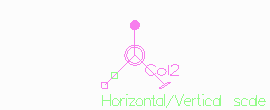
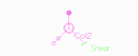
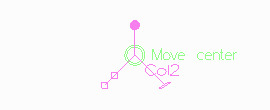
- Mode:, lets you choose which transformation options to display in the tool options bar. Options are: Position, Rotation, Scale, Shear, Center and All.
- Position, X: and Y: set the horizontal and vertical positions of the selected object, Z: sets its position along the Z axis, for defining the depth of the object in 3D space (see Working in a 3D Environment ), and SO: sets the column/layer stacking order, that can override the default one defined by the Xsheet column (or Timeline layer) order (see Changing Columns Stacking Order ).
- Rotation:, sets the rotation of the selected object around the Z axis.
- Scale, Global:, H: and V: set the global, horizontal and vertical scaling of the selected object. Maintain: sets a constraint for scaling operations performed by using the Animate tool handle: if it is set to A/R the object will maintain its proportions, if it is set to Mass the object will maintain its overall volume.
- Shear, H: and V: set the horizontal and vertical shearing of the selected object.
- Center, X: and Y: set the horizontal and vertical position of the center of the selected object. The Center of an object cannot be animated.
- All displays all transformation types at the same time. In the viewer a handle will also be available that let users visually change any of the transformation types: Position, Rotation, Scale, Shear and Center.
- Pick: (only available in All mode) lets the user choose to automatically select columns/layers or pegbars to be animated when the selection is done by clicking in the Viewer: when set to Column, clicking a drawing automatically selects the related column/layer; when set to Pegbar, clicking a drawing automatically selects the pegbar to which the column/layer containing the drawing is linked (if there is one); when set to None the selection of drawings in the Viewer is disabled.
- Lock buttons (
) define which values remain locked while transforming the object.
- Global Key when activated, sets a key for all of the object transformations as soon as a key is set for any of its transformations interactively in the viewer. For example if you change the position of an object, thus defining a keyframe for it, keys will also be automatically defined for the rotation, scaling and shearing transformations as well. This option will not take any effect if the values for the property are input directly in the toolbar, and not interactively.


Note
If the tool options bar is too short to display all the tool options, it can be scrolled by using arrow buttons available at its ends.
Note
Position values are expressed in the default unit of measure set in the Preferences… → Interface dialog (see Choosing the Working Unit ).
Animate Tool Handle
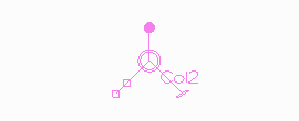
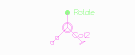
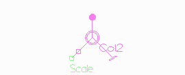
When the Animation tool is in All mode, you can also interactively control transformation values by using the handle available in the viewer. The handle is made of an inner double circle with three arms that allow you to change any of the following transformations:
Note
As you roll over the handles, the cursor changes shape to indicate to you the operations you may perform.
Note
For greater precision it is possible to keep the Alt key depressed before starting to perform any transformation.
- Position: Click and drag anywhere to move the object; if the Shift key is pressed while dragging, the movement will be constrained in the horizontal or vertical direction.
- Rotate: Click and drag the circle end to rotate the object;
- Scale: Click and drag the outer square of the double-square end to scale the object uniformly on the vertical and horizontal; click and drag the inner square of the double-square end to scale the object according to the constraint set in the options bar; if no constraint is set and the Shift key is pressed while dragging, the scaling will be uniform.
- Shear: Click and drag the parallelogram end to shear the object; if the Shift key is pressed while dragging, the shearing will be constrained in the horizontal or vertical direction.
- Center: Click and drag the double circle at the center to change the center of the object.
Note
The object center can be moved, but cannot be animated. Once it is set, or modified, it is retained in that position during all of the animation. If the Center is changed many times, and you want to set it back to its original position, right-click the object in the Stage Schematic and choose Reset Center from the menu that opens.
When entering a value or operating the handle, a keyframe will be automatically generated at the current frame only for the set transformation; if the Global Key option is activated, keys will be generated for all of the transformations.
If you want to set a key for an object transformation, maintaining its value as it is at the current frame, you can just press Enter on the displayed value. If you want to set keys for all of the object transformations maintaining their values as they are at the current frame, you can use the Set Key button ( ) available in the bottom bar of the viewer; in this case keys are created for all of the object transformations, regardless of the Global Key option.
Note
Objects can also be animated by working in the Function Editor (see Editing Curves and Numerical Columns ).
Note
The movement of the column contents can be checked by activating the Onion Skin mode, as it will display the position of drawings contained in the current column at different frames (see Using Onion Skin ).
Tip
To select the object to edit:
Do one of the following:
- Select it in the stage schematic.
- If the object is a column/layer, select it in the Xsheet/Timeline.
- Use the Animate tool () with the Pick: option set to Column to click a drawing in the viewer to select the related column.
- Use the Animate tool () with the Pick: option set to Pegbar to click a drawing in the viewer to select the pegbar that the column containing the drawing is linked to.
- Right-click in the Viewer a drawing to select an object from the list of scene objects.
Tip
To animate an object with the Animate tool:
- Select the object you want to animate.
- Choose the Animate tool ().
- Set the frame where you want to define the key by doing one of the following:
- Move the current frame cursor in the Xsheet/Timeline or in the Function Editor.
- Use the Frame bar or the Playback buttons in the bottom bar of the viewer.
- When animating columns only, select the related cell in the column/layer.
- Define a keyframe.
- Select a different frame, and go on defining keyframes.
Tip
To define a keyframe only for some object transformations:
- Deactivate the Global Key option in the tool options bar.
- Do one of the following:
- Enter values in the Animate tool options bar for the object transformations you want to set a key for.
- If in All mode, operate the handle to move, scale, rotate or shear the object, automatically generating a key only for the modified transformation.
Note
As this keyframe is partial and refers only to some transformations, the Set Key button turns striped-blue.
Tip
To define a keyframe for all the object transformations:
- Activate the Global Key option in the tool options bar.
- Interactively move, rotate, scale or shear the object in the viewer.
Note
As this keyframe is global and refers to all the transformations, the Set Key button turns blue.
Tip
To define a key for an object transformation leaving its value as it is at the current frame:
- Deactivate the Global Key option in the tool options bar.
- In the Animate tool options bar click in the field of the object transformations you want to set a key for, and press the Enter key.
Note
As this keyframe is partial and refers only to some transformations, the Set Key button turns striped-blue.
Tip
To define keys for all of the object transformations leaving their values as they are at the current frame:
Do one of the following:
- Click the Set Key button ().
- When animating columns/layers only, right-click in the column/layer cell and choose Set Key from the menu that opens.
Note
As this keyframe is global and refers to all the transformations, the Set Key button turns blue.
Tip
To turn a partial keyframe to a global key:
Click the Set Key button (): it turns from blue-striped to blue.
Tip
To remove a set keyframe from the viewer bottom bar:
Do one of the following:
- If the keyframe is global, click the Set Key button (): it turns from blue to grey.
- If the keyframe is partial, click twice the Set Key button (): with the first click it turns from striped-blue to blue, with the second from blue to grey.
Tip
To navigate frames where keyframes are defined in the viewer bottom bar:
Use the Previous Key ( ) and Next Key (
 ) buttons available at the side of the Set Key button.
Note
Keys can also be removed or navigated by working in the Function Editor (see Editing Curves and Numerical Columns ).
Tip
To customize the Animate tool options bar:
Do any of the following:
- Use the Tool Mode: dropdown menu to choose from one of its modes: Position, Rotate, Scale, Shear, Center or All: only the options for the selected transformation category will be displayed.
- Use the Lock button () to choose which transformations have to be locked while transforming the object: only selected items will be locked.
Changing Stacking Order of Columns/Layers
The column/layer stacking order, which sets which drawings and images are placed on top or behind, other images, by default depends on how columns/layers are placed in the Xsheet/Timeline: Xsheet direction is from left to right, while Timeline direction is from bottom to top, making what’s on the left/bottom to be behind of what’s on the right/top.
This would mean that if an animation element has to move behind another animation element and then in front of it, it’d have to be exposed in two different columns, one before and one after the column containing the second animation element.
By editing the SO (i.e. stacking order) value it’s possible to change and animate the element compositing order without editing the columns/layers position in the Xsheet/Timeline.
The SO default value for all the columns is 0, meaning that the Xsheet column (or Timeline layer) order is what’s taken into account when there are no modifications to the SO position. As soon as a column/layer has a higher SO value, it will be placed on top, regardless of the position of the column/layer in the Xsheet/Timeline; conversely if the SO value is lower it will be placed behind.
Note
In case a column/layer’s Z position is edited, columns/layers closer to the camera will be composited on top of others, ignoring both its Xsheet/Timeline order and its SO value (see Working in a 3D Environment ).
Tip
To edit and animate a column/layer SO value:
- Select the column/layer to which you want to edit the SO value.
- Choose the Animate tool ().
- Set the frame where you want to define the key.
- In the tool options bar enter the value in the SO field.
Note
Columns/layers SO values can also be edited and animated by working in the Function Editor (see Editing Curves and Numerical Columns ).
Creating a Movement along a Motion Path
Objects can be moved along a motion path according to two different type of movements: one without changing the object orientation, and the other with an automatic orientation, set according to the direction of the motion path.
A motion path can be assigned to an object node in the Stage Schematic, and it can be defined with drawing tools and edited in the viewer as if it was a vector drawing. Once defined, it’s displayed as a dashed red line, with small numbers indicating the control points defining the vector stroke.
A motion path assigned to pegbar 2.
As soon as a path is assigned to an object’s node, the object will be automatically placed at the beginning of the path according to its center, and it will only be able to move along it (and not in the standard X and Y directions anymore).
The keyframes of the object on the motion path can be defined by dragging the object along it, and they are expressed as a percentage where 0% is the starting point and 100% is the ending point of the path.
It’s also possible to link the keyframes of the objects to the positions of the control points defining the motion path, so that they remain consistent when the motion path is edited. To help you better understand where the control points are, the object snaps to them when it is dragged along the motion path.
Note
If you want to change the center of the object, you can move it using the Animate tool (), and then use the Reset Center command in the Stage Schematic.
Note
A motion path can also be created by copying and pasting a drawing vector stroke, and conversely a drawing vector stroke can be created by copying and pasting a motion path.
Tip
To create a motion path:
- Select the object for which you want to define a motion path.
- Do one of the following:
- Click the New Motion Path button (
 ) in the bottom bar of the stage window.
 - Right-click in the stage and choose New Motion Path from the menu that opens.
Tip
To define and edit a motion path:
Select the motion path node in the stage and do any of the following:
- Use the drawing tools to define it in the viewer.
- Use the modifier tools to edit it.
- Draw a new line, and confirm in the dialog that opens, to replace a previously created motion path with the new one.
Tip
To assign a motion path to an object:
Click and drag the motion path top port to the object node bottom port.
Tip
To remove a motion path from an object:
- Select the link between the object and the motion path.
- Choose Edit → Delete.
Tip
To set the type of movement along a motion path:
Click the button at the far left of the object bottom port to switch between two options: the Square button ( ) will preserve the object’s original orientation, and the Rotated Square button (
 ) will automatically rotate the object according to the motion path’s direction.
Tip
To link the object keyframes to the control points defining the motion path:
Click the button next to the object bottom port to activate or deactivate the Link to Control Points option ( ).
).
Tip
To change the center of the object:
- Choose the Animate tool ().
- Move the center of the object to the new position.
- Right-click the object node in the Stage Schematic and select Reset Center from the menu that opens.
Tip
To save a motion path:
- Right-click it and select Save Motion Path from the menu that opens.
- In the browser choose a location and a name and click the Save button. The file will be saved with the MPATH extension.
Tip
To load a motion path:
- Right-click the motion path and select Load Motion Path from the menu that opens.
- In the browser retrieve the MPATH file you want to load and click the Load button.
Tip
To use a drawing vector stroke as a motion path:
- Select the vector stroke you want to use as a motion path with the Selection tool (
 ).
). - Copy/cut it.
- Select the motion path you want to paste to, in the Stage Schematic.
- Click in the viewer and paste the copied/cut vector that will automatically become the motion path.
Tip
To use a motion path as a vector stroke in a drawing:
- Select the motion path in the Stage Schematic.
- Select the motion path with the Selection tool () in the viewer.
- Copy/cut it.
- Select the drawing where you want to paste the new stroke.
- Paste the copied/cut motion path that will automatically become a stroke.
Tip
To remove a motion path from the Stage Schematic:
Do one of the following:
- Select the motion path node and choose Edit → Delete.
- Right-click the motion path node and choose Delete from the menu that opens.
Using Keys in Columns/Layers
When columns/layers are animated, their animation can be controlled in a quick way by managing keyframes and interpolations directly in the Xsheet or Timeline, with no need to use the Function Editor.
As soon as a keyframe is defined for a column/layer, a Key icon is displayed on the right of the column/layer cell to which it refers; the key is displayed regardless of how many parameters are animated. Keys can be moved within the column/layer they refer to, and selected in order to be cut/copied and pasted from one cell to another.
When the Global Key option is activated for the Animate tool, and the default interpolation is not set to Linear, as soon as at least two keyframes are created for a column, a line connecting them with two arrowheads is displayed (see Animating Objects and Setting Segment Interpolations ). The two arrowheads divide the line into three sections indicating the speed in, the constant speed, and speed out phases of all the transformations defined. This allows you to control the speed of the movement between the two keys as you wish, including a constant speed movement.
You can also cycle previously created keys, in order to repeat automatically all the previously defined keys for the whole length of the scene, with no need to copy and paste keys from cells to cells.
All animations and interpolations set for the column/layer can be visible and edited with the Function Editor. When you edit any column/layer transformation in the Function Editor, the arrowheads will not be displayed anymore between keys, to stress the fact that a specific interpolation has been modified with the Function Editor. If needed, you can Reset the whole column/layer transformation to the default interpolation values, and make the arrowheads available again (see Editing Curves and Numerical Columns ).
Tip
To modify a key:
- Select the cell the key refers to.
- Do one of the following:
- Use the Animate tool () to modify position and size.
- Enter values you want to modify in the Animate tool () options bar.
Tip
To select keys:
Do one of the following:
- Click a key icon to select it.
- Click a key icon and drag to select a range of keys on different columns and at different frames.
- Shift-click to extend the selection to a specific key.
- Ctrl-click (PC) or Cmd-click (Mac) to add to, or remove a key to the selection.
- Right-click a key icon and choose the related command from the menu that opens to perform specific selections, such as all keys in the row, all previous ones, all following ones, etc.
Tip
To move a key selection:
Click any of the selected keys and drag the selection to the new position. Dragging is allowed only inside its own column/layer.
Tip
To edit a key selection:
Do one of the following:
- Use the Cut command to eliminate the selection from the scene and keep it in memory for further operations.
- Use the Copy command to keep the selection in memory for further operations.
- Use the Paste command to paste the selection kept in memory starting from the selected cell.
- Use the Delete command to delete the selection.
Note
All these commands are also available in the menu that opens when right-clicking the key icon.
Tip
To set the speed of the movement or transformation:
Click the arrowheads available on the line connecting two subsequent keys, and drag them up or down to the new position. In particular:
- To set a constant speed, drag the top arrowhead close to the first key icon to eliminate the ease in section, and the bottom arrowhead close to the second key icon to eliminate the ease out section.
- To set a continuous acceleration, drag both arrowheads close to the second key icon in order to increase the speed in section.
- To set a continuous deceleration, drag both arrowheads close to the first key icon in order to increase the speed out section.
Tip
To make the arrowheads available when they are not:
Right-click the line connecting two subsequent keys and choose Reset Interpolation from the menu that opens.
Tip
To activate/deactivate the cycling of previously created keys:
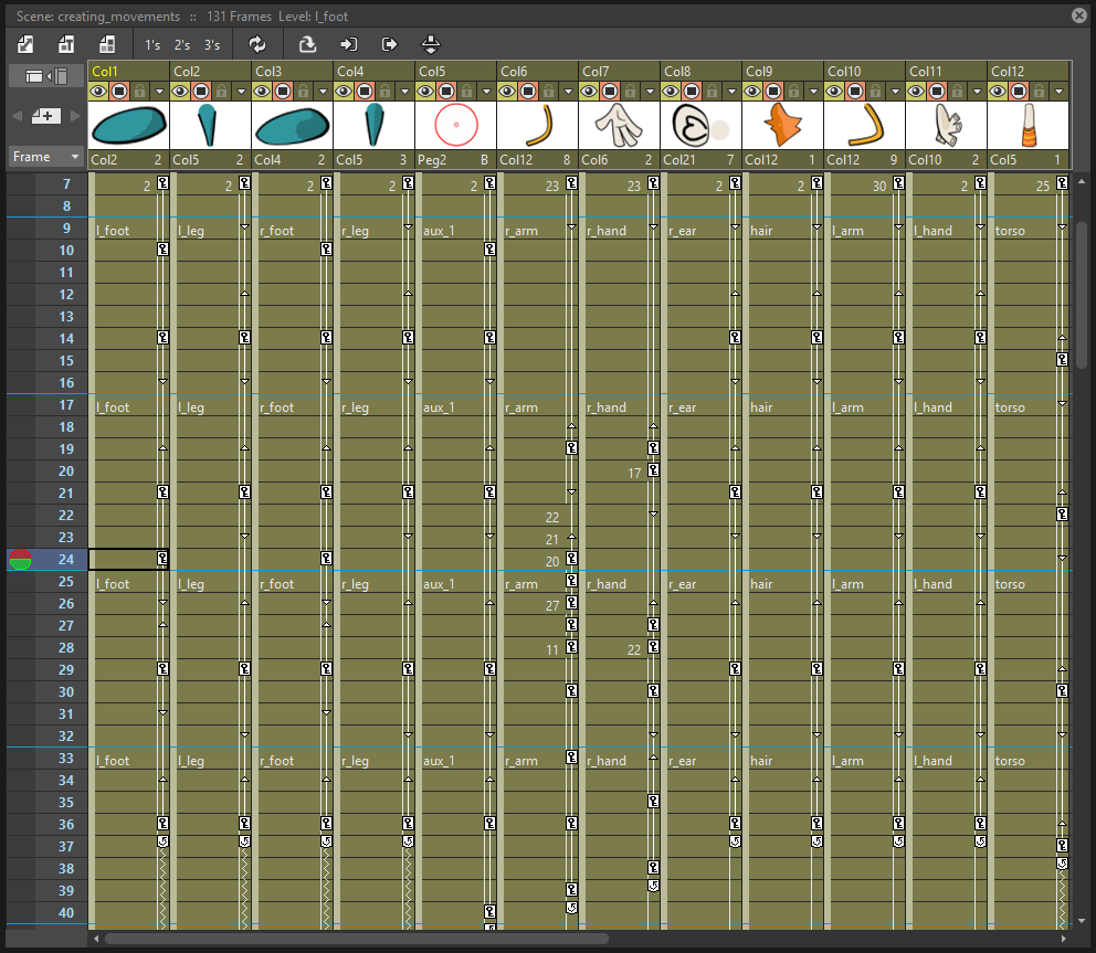
Click the Circular arrow icon (![]() ) visible after the last key of a series.The cells affected by the cycled movement are marked on the right by a zigzagged line.
) visible after the last key of a series.The cells affected by the cycled movement are marked on the right by a zigzagged line.
Tip
To open the Function Editor:
Do one of the following:
- Double-click a key.
- Right-click a key and choose Function Editor from the menu that opens.
Working with Multiple Column/Layer Keys
It is possible to insert or delete keys affecting the Xsheet/Timeline as a whole, or a selection of Xsheet columns (or Timeline layers).
Inserting or deleting multiple keys allows you to manage keys for several columns/layers at the same time, for instance when you are working on a cutout animation where keys may be required for all the columns/layers where model sections are exposed (see Creating Cutout Animation ).
Note
Inserted keys are created for all the column transformations.
When a multiple key is inserted at the current frame, a key is created for each Xsheet column (or Timeline layer) where an animation level is exposed; if a column/layer selection is defined, keys are created in selected columns/layers only (see Working with Xsheet Columns ).
When a multiple key is deleted at the current frame, any key available in any Xsheet column (or Timeline layer) at the current frame is deleted; if a column/layer selection is defined, keys are deleted in selected columns/layers only.
Tip
To create several keys at once:
- Do one of the following:
- Select the columns/layers for which you want to create keys.
- Select no column by clicking anywhere in the Xsheet/Timeline, to create keys for all the columns/layers.
- Select the frame where you want to insert keys.
- Choose Xsheet → Insert Multiple Keys.
Tip
To remove several keys at once:
- Do one of the following:
- Select the columns/layers from which you want to delete keys.
- Select no column by clicking anywhere in the Xsheet/Timeline, to delete keys from all the columns/layers.
- Select the frame where you want to delete keys.
- Choose Xsheet → Remove Multiple Keys.
Working in a 3D Environment
You can place and move cameras, the table, pegbars and columns/layers in a 3D environment, as if they were elements on a real 3D stage.
This means that it’s possible to move the camera automatically generating a multiplane effect, or truck it through characters and elements simulating a perspective effect, or create complex 3D motion paths for any element by combining a depth movement with movements in the X and Y directions.
The 3D environment can be activated, or deactivated, with the 3D View button ( ) available in the Viewer title bar. When activated, the viewer displays the cone of the camera and all of the scene contents along the Z axis, which is the direction from the camera to the table. The area displayed can be moved and rotated to set the best viewing angle, and a side or top viewpoint can be set.
By default all the pegbars and columns are on the table: their Z position is equal to the number of horizontal fields defined for the default camera (as the value represents the size of the area that is shot by the camera) (see Defining Camera Settings ). By increasing the field value, objects are placed farther from the camera; by decreasing it, objects are placed closer to the camera; at zero they are at the same Z position as the camera, and for negative values they are behind the camera.
As concerning the camera, by default its Z position is equal to the number of horizontal fields defined for the default camera. By increasing the field value, the camera moves farther from the table; by decreasing it, it moves closer; at zero it is at the same Z position of the table and for negative values it is behind the table.
As soon as objects are moved, projections on an imaginary floor and side wall let you understand the position of the drawings in relation to each other and to the camera. If the current object is a column/layer, a dotted bounding box displays the area of it currently being shot by the camera.
The size of the objects changes according to its Z position, like in a real 3D environment, decreasing when an object is farther from the camera and increasing when closer. To keep control of this behaviour it’s possible to define an additional Z position value in the tool options bar, that sets the position at which the object has to keep its original size.
Note
Columns closer to the camera are displayed on top of others, ignoring the Xsheet/Timeline order and the SO value. In case two or several columns have exactly the same distance, the SO value prevails; if two or several columns have exactly the same distance and SO value, the Xsheet column (or Timeline layer) order prevails (see Changing Columns Stacking Order ).
Tip
To enter the 3D environment:
Click the 3D View button () available on the right of the viewer title bar.
Tip
To set an object position in the 3D environment:
- Activate the 3D View.
- Select the object you want to move.
- Select the Animate tool ().
- Do one of the following:
- Enter a value for the Z position in the tool options bar.
- Use the double-arrow handle parallel to the floor of the 3D environment, to move the selected object and set its Z position.
Tip
To set at which position the object has to keep its original size:
Enter a value for the additional Z position field displayed in brackets in the tool options bar. For example if you want a column content to keep its original size when placed at the Z position 8, also enter 8 as the value in brackets.
Tip
To move the work area displayed in 3D:
Select the Hand tool ( ) and drag in the viewer.
Tip
To rotate the work area displayed in 3D:
Select the Rotate tool ( ) and drag in the viewer.
Tip
To set a side or a top view:
Do one of the following:
- To set a Side view use the button (
 ) available on the side wall of the 3D environment.
 - To set a Top view use the button (
 ) available on the floor of the 3D environment.
Tip
To exit the 3D environment:
Click the Camera Stand () or Camera View ( ) buttons available on the right of the viewer title bar.