Applying Effects
Effects can be applied to animation levels, images and clips exposed in Xsheet columns (or Timeline layers) in the FX Schematic, where each element is represented as a node.
The relationship between the contents of columns/layers and effects can be managed by connecting or disconnecting links between nodes.


Using the FX Schematic
In the FX schematic all columns/layers are displayed as nodes having an output port connected to the Xsheet node: this means that their content is part of the scene and is rendered as it is.
When effects are added, they are displayed as nodes as well, with ports to create links that let you set the way the effect modify the scene contents.
Column/layer nodes have the Camera Stand ( ) and the Render (
 ) toggles on the top right: these toggles are the same as the toggles available in the Xsheet column (or Timeline layer) headers (see Working with Xsheet Columns ). Effects nodes only have the Render toggle () allowing you to include or exclude temporarily the effect in the rendering.
Nodes can be easily selected and arranged. When selected, nodes are highlighted in white; the current node has its label in yellow.
نکته
To access the FX Schematic:
Click the Schematic toggle button ( ) at the right of the bottom bar of the Schematic window until the title bar displays FX Schematic.
نکته
To navigate the FX Schematic:
Do one of the following:
Use the mouse wheel, or the zoom shortcut keys (by default + and - keys) to zoom in and zoom out.
Middle-click and drag to scroll in any direction.
Use the Fit to Window button (
 ) in the bottom bar of the Schematic window to display all of the nodes in the current window.
Use the Focus on Current button (
 ) in the bottom bar of the Schematic window to center the Schematic on the current node.
Use the Reorder Nodes button (
 ) in the bottom bar of the Schematic window to reorder all the nodes.
Use the Reset Size button (
 ) in the bottom bar of the Schematic window, or use the Reset View shortcut (by default the Alt + 0 key) to display all of the nodes at the default size.
نکته
To rename a node:
Ctrl + double-click the node name and type a new name.
نکته
To minimize or maximize the column/layer and effect nodes:
Do one of the following:
Click the arrowhead to the left of the node name to minimize/maximize columns selectively.
Click the Minimize/Maximize (
 /
/ ) button in the bottom bar of the Schematic window to minimize/maximize all the column nodes.
نکته
To select nodes:
Do one of the following:
Click to select a node.
Click and drag to select a group of nodes.
Ctrl-click (PC) or Cmd-click (macOS) to add a node to, or remove it from the selection.
توجه
Links can be selected together with nodes (see Editing the FX Schematic ).
نکته
To move the selection:
Click and drag any node of the selection.
نکته
To include or exclude temporally an effect from the rendering:
Click the Render toggle () on the upper right corner of the effect node.
Grouping Nodes
It's possible to group several nodes into one single node, in order to better manage the whole FX Schematic. Groups can be opened to be examined and edited, and its components can be selected for further operations, like editing effect settings, or creating new groups.
نکته
To Group selected nodes:
Do one of the following:
Right-click any selected node and choose Group from the menu that opens.
Press the Ctrl-G (PC) or Cmd-G (macOS) shortcut.
نکته
To open a Group:
Right-click the group and choose Open Group from the menu that opens: the group nodes are displayed in a box, showing links between group nodes, and links with nodes outside of the group.
توجه
In the FX Schematic, when the content of a group is displayed, it's possible to edit the links between Group nodes and links with nodes outside of the group.
نکته
To close a Group:
Click the Close button on the right of the group box title bar.
نکته
To release a Group:
Right-click the Group and choose Ungroup from the menu that opens, or press the shortcut Ctrl-Shift-G (PC) or Cmd-Shift-G (macOS).
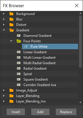
Inserting Effects
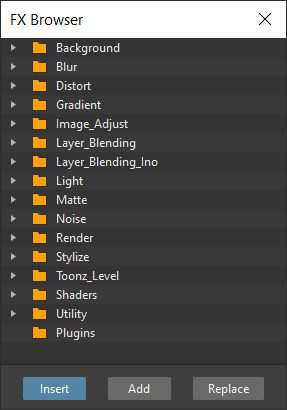
You can Insert effects to selected nodes, Add effects to the Schematic, or Replace previously added effect nodes. This can be done from the FX Browser window or by using the drop-down menu that opens when right-clicking nodes or an empty area of the FX Schematic. Both are organized in folders/submenus containing sets of effects; if some Presets are defined for an effect, an additional folder/submenu is available (see Creating Presets ).
When inserting effects, they will be placed along the link that starts from the selected node output port; when adding effects, they will be placed at the end of a new link that will start from the selected node output port.
In case several nodes are selected, the effect will be added/inserted for each selected node, but all the added/inserted effects will be Linked, and connected visually by a green line. This means that every time the effect is edited, all the linked nodes will be edited as well, unless you break the link to start editing them separately.
To globally apply effects it's possible to use the Xsheet node as if it were a standard column node (representing the whole content of the scene) and inserting effects from there.
Three different types of effects can be used in the Schematic, each with a different type of node:
Basic effects, such as the Blur effect, that simply modify the contents of a column; they are displayed as a yellow node with an input port on the left, labelled Source, and an output port on the right.
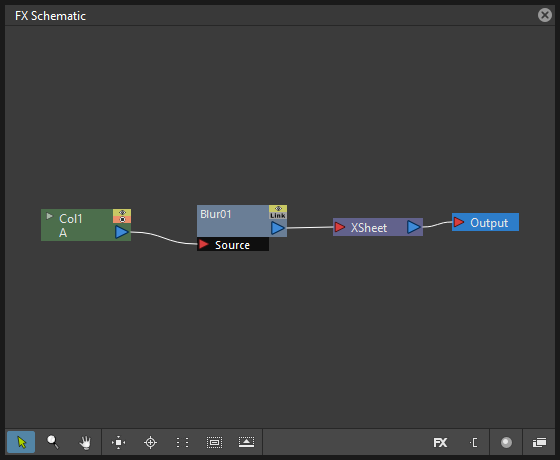
To affect a column/layer, they have to be inserted in the link from the column/layer node to the Xsheet node, so that the column/layer node is connected to the effect input port, and the effect node output port is connected to the Xsheet node.
If several effects are applied in a chain, they will be applied one after the other, following the order from the column/layer node to the Xsheet node.
Combined effects, such as the Matte In effect, that modify the column/layer contents according to the contents other columns/layers; they are displayed with a yellow node with two or more input ports on the left, and one output port on the right.
To affect a column/layer, they have to be inserted into the link from the column/layer node to the Xsheet node, so that the column/layer node is connected to the first effect input port labelled Source, while the other columns/layers are connected to the other input ports, whose labels depend on the effect; the effect node output port has to be connected to the Xsheet node.
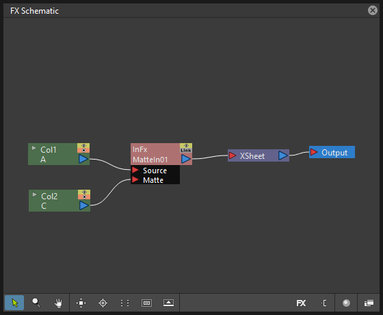
For example in case of a Matte In effect, the column to be matted has to be linked to the Source input port, the matte column has to be linked to the Matte input port, and the output port has to be connected to the Xsheet node.
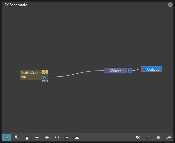
Effects that create computer generated images, such as the Radial Gradient, that are exposed in Xsheet columns (and Timeline layers) and therefore are similar to columns; they are displayed with an orange node with only an output port on the right. These effect nodes have to be connected to the Xsheet node to be rendered, or can be connected to other effect nodes.
نکته
To open the FX Browser:
Do one of the following:
Choose Xsheet → New FX...
Click the New FX button (
 ) in the bottom bar of the FX Schematic window.
نکته
To Insert an effect:
Do one of the following:
Select the nodes for which you want to insert a new effect, select the effect you want to insert in the FX Browser and click the Insert button.
Select the nodes for which you want to insert a new effect, right-click any of them and choose Insert FX from the menu that opens, then select the effect you want to insert from the available submenus.
Select the links where you want to insert a new effect, right-click any of them and choose Insert FX from the menu that opens, then select the effect you want to insert from the available submenus (see Editing the FX Schematic ).
نکته
To Add an effect:
Select the nodes for which you want to add a new effect at the end of a new link.
Do one of the following:
Select the effect you want to add in the FX Browser and click the Add button.
Right-click any of the selected nodes and choose Add FX from the menu that opens, then select the effect you want to add from the available submenus.
نکته
To Replace an effect:
Select the effect nodes you want to replace with a new effect.
Do one of the following:
Select the effect you want to add in the FX Browser and click the Replace button.
Right-click any of the selected nodes and choose Replace FX from the menu that opens, then select the new effect from the available submenus.
نکته
To Insert/Add effects globally:
Select the Xsheet node.
Do one of the following:
Select the effect you want to insert/add in the FX Browser and click the Insert or Add buttons.
Right-click any of the selected nodes and choose Insert FX or Add FX from the menu that opens, then select the effect you want to a insert/add from the available submenus.
نکته
To rename a node:
Ctrl + double-click (PC) or Cmd + double-click (macOS) the node name and type a new name.
Editing the FX Schematic
Links between nodes have to be considered like flows going to the right, from the column/layer nodes to the Output node, via the Xsheet node. If along the way there is one or several effects, the column content will be consequently processed before becoming part of the output.
From the nodes output port several links can start at the same time, thus allowing, for example, a column/layer to be rendered as it is, and to be also used as a mask for another column/layer. It is also possible to determine permanently whether columns/layers will be rendered or not, by leaving or deleting the link to the Xsheet node.
By editing the links between nodes, or by creating new ones, you can control how column/layer nodes will interact with each other and with effects before being rendered.
توجه
In the effects that accept multiple input nodes it is possible to change the stacking order of the input nodes by clicking and dragging in the ports area.
Effect nodes and links can be selected in order to be cut, copied, pasted or deleted. When selected, nodes and links are highlighted in white; the current node has its label in yellow; when at least one object is selected, the related links are displayed in blue.
When pasting a copied/cut selection, several options are available:
Use Paste to paste the copied/cut selection into the FX Schematic.
Use Paste Insert to insert the pasted selection into the selected links.
Use Paste Add to add the pasted selection from the selected nodes at the end of new links.
Use Paste Replace to replace selected effects nodes with the pasted selection.
توجه
Links have to be selected together with nodes when copying/cutting a selection if you want to preserve the links among them when pasting.
نکته
To create links between nodes:
Click and drag the output port of the node to the input port of the effect node.
نکته
To select nodes and links:
Do one of the following:
Click to select a node or a link.
Click and drag to select a group of nodes and links.
Ctrl-click (PC) or Cmd-click (macOS) to add a node or a link to, or remove it from the selection.
نکته
To delete links between nodes:
Select the links you want to delete and do one of the following:
Choose Edit → Delete.
Right-click any selected link and choose Delete from the menu that opens.
نکته
To connect a node to the Xsheet node:
Do one of the following:
Click and drag the output port of the node to the input port of the Xsheet node.
Right-click the node you want to connect to the Xsheet node, and choose Connect to Xsheet from the menu that opens.
نکته
To disconnect a flow from the Xsheet node:
Do one of the following:
Delete the link from the node to the Xsheet node.
Right-click the node you want to disconnect from the Xsheet node, and choose Disconnect from Xsheet from the menu that opens.
نکته
To insert an effect node into a link:
Alt-click and drag it onto the link.
نکته
To extract an effect node from a link:
Alt-click and drag it away from the link.
نکته
To edit an effect nodes selection:
Do one of the following:
Use the Copy command to keep the selection in memory for further operations.
Use the Cut command to eliminate the selection from the schematic and keep it in memory for further operations.
Use the Paste command to paste the selection kept in memory in the FX Schematic.
Right-click a link and use the Paste Insert command to insert the selection kept in memory into the selected link.
Right-click any node and use the Paste Add command to add the selection kept in memory from the selected nodes at the end of the new links.
Right-click an effect node and use the Paste Replace command to replace the selected effect nodes with the selection kept in memory.
Use the Delete command to delete the selection.
توجه
All these commands are available in the menu that opens when right-clicking nodes and links.
نکته
To create a linked effect:
Select the effect nodes you want to duplicate.
Right-click any of the selected nodes and choose Create Linked FX from the menu that opens.
نکته
To break linked effects:
Select the effect nodes you want to unlink.
Right-click any of the selected nodes and choose Unlink from the menu that opens.
Using Multiple Output Nodes
In the FX Schematic by default the Xsheet node is connected to an Output node: this means that all the nodes connected to the Xsheet node will be rendered both in the preview and in the final rendering.
The scene rendering can be limited to a specific node of the schematic by creating additional Output nodes, connected to the node where you want to limit the rendering.
When more than one Output node is defined, you can set which is the active one (the one that will be considered for previewing or rendering the scene); the active output node is displayed in blue, while the others in grey.
نکته
To limit the output to a specific node:
Select the node to which you want to limit the output.
Do one of the following:
Click the New Output button (
 ) in the bottom bar of the schematic window.
Right-click the node and choose New Output from the menu that opens.
نکته
To add an Output node:
Do one of the following:
Click the New Output button (
) in the bottom bar of the schematic window.Right-click in the schematic and choose New Output from the menu that opens.
نکته
To connect a node to an Output node:
Click and drag the output port of the node to the input port of the Output node.
نکته
To set the current Output node:
Right-click the Output you want to set as current and choose Activate from the menu that opens.
نکته
To remove an Output node:
Do one of the following:
Select it and choose Edit → Delete.
Right-click it and choose Delete from the menu that opens.
توجه
The last Output node remaining cannot be removed from the Schematic.
Editing Effects Settings
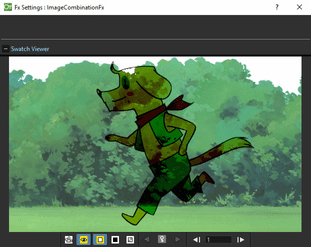
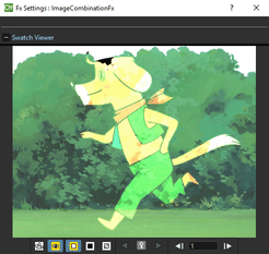
Effects parameters and their animation can be controlled in the FX Settings window. According to the selected effect, it displays a different layout of sliders, check boxes, text fields, etc.
At the bottom of the window a preview area is available to check the result of the applied effect: you can expand it or contract it, activate it or deactivate it, navigate its content, set its size, its background color, and limit it to the camera shot. The preview area can be expanded or contracted by clicking on the +/- symbol to the left of the Swatch Viewer text, at the bottom left of the FX Settings window.
Parameters can be animated by setting keyframes at specific frames. A Set Key button ( ) is available in the preview area, at the bottom bar of the window, to set keyframes for all of the parameters. For each of the parameters that can be animated there is also a specific Set Key button () to the right of the parameter name, in order to set keyframes for each parameter independently.
The Set Key button () may have the following colors:
It is grey when no keyframes for any parameter is defined at the current frame.
It is blue-striped when keyframes are defined at least for one parameter.
It is blue when keyframes are defined for all the parameters.
The parameter specific Set Key button () may have the following colors:
It is grey if no key value is defined for the parameter at the current frame.
It is orange when a key value is defined for the parameter at the current frame.
It is pale yellow if the parameter is animated but no key value is defined at the current frame.
It is yellow if you changed the parameter value and the current frame does not have a key for the parameter.
Frames and keyframes can be navigated by using the related buttons in the bottom bar of the window. The Next Key ( ) and Previous Key buttons (
 ) are available only if more than one keyframe is defined.
If no keyframes are defined, parameters you set will be used throughout the scene.
نکته
To open the FX Settings window:
Do one of the following:
Right-click the effect node, and choose Edit FX... from the menu that opens.
Double-click the effect node.
نکته
To define values for the effect:
Use the available sliders, check boxes, text fields, etc., to configure the effect the way you prefer.
نکته
To set the current frame:
Do one of the following:
Type the frame number or use the Next Frame and Previous Frame buttons available in the bottom bar of the window.
Move the current frame cursor in the Xsheet/Timeline or in the Function Editor.
Use the frame bar or the playback buttons in the bottom bar of the Viewer.
نکته
To set keyframes for all the effect parameters at the current frame:
Do one of the following:
If the current frame is not a key, click the Set Key button (
) in the bottom bar of the window: it turns from grey to blue and current values become keyframes for all the parameters at the current frame.If the current frame is a keyframe for some parameters only, click the Set Key button (
): it turns from blue-striped to blue and current values become keyframes for all the parameters at the current frame.
Define the values for the parameters.
نکته
To set keyframes for a specific parameter at the current frame:
If the current frame does not have a keyframe for the parameter, click the squared Set Key button (
) to the right of the parameter: it turns from grey to orange, and the current value becomes a keyframe for the parameter at the current frame.Define the value for the parameter.
توجه
If the current frame is not a keyframe for the parameter, and you changed it, the Set Key button () to the right of the parameter turns yellow. Click it to set the key.
نکته
To remove all keyframes for the effect parameters at the current frame:
Do one of the following:
If the keyframes are set for all the parameters, click the Set Key button (
) in the bottom bar of the window: it turns from blue to grey.If the keyframes are set for some parameters only, click twice the Set Key button (
) in the bottom bar of the window: with the first click it turns from blue-striped to blue (as you set keys for all the parameters); with the second click, it turns from blue to grey.
نکته
To remove a keyframe for a specific parameter at the current frame:
Click the Set Key button () to the right of the parameter: it turns from grey to orange.
نکته
To navigate frames where keyframes are defined:
Use the Next Key () and Previous Key buttons () available at the side of the Set Key button.
نکته
To activate/deactivate the preview:
Do any of the following:
Click the Camera Preview button (
 ) in the bottom bar of the FX Settings window to limit the preview to the camera shot.
Click the Preview button (
) in the bottom bar of the FX Settings window to preview the results regardless of the camera shot.
نکته
To resize the preview area:
Do any of the following:
Click and drag the horizontal separator.
Click and drag the separator toward the window border to hide the preview area.
Click and drag the separator collapsed to the window border toward the window center to display again the preview area.
توجه
The A/R of the preview area depends on the A/R of the current camera.
نکته
To change the background color of the preview area:
Use the buttons in the bottom bar of the FX Settings window to choose a White ( ), Black (
 ) or Transparent (
 ) background.
نکته
To navigate the preview area:
Do one of the following:
Use the mouse wheel, or the zoom shortcut keys (by default + and - keys) to zoom in and zoom out.
Middle-click and drag to scroll in any direction.
Use the Reset View shortcut (by default the Alt + 0 key) to display preview at its actual size.
Using Effects Gadgets
Some effects parameters related to positions or dimensions have some gadgets available in the Viewer in order to be set by using the camera box and the scene elements as a reference. For example the Radial Gradient effect has two circular gadgets that can be edited to set the inner size and the outer size of the gradient.
As soon as an effect node is selected in the schematic, the Animate tool becomes the current tool and the related effect gadgets, if available, are shown. The Animate tool settings will refer to the column the effect is applied to, but in case the effect creates a computer generated image (e.g. a radial gradient or a light spot) the settings will refer to the effect column itself (see Animating Objects ).
نکته
To visualize effects gadgets in the Viewer:
Select the effect node in the FX Schematic.
نکته
To edit effects gadgets:
Click and drag the effects gadgets visible in the Viewer. As you roll over the gadget and the related handles, the cursor changes shape to indicate you are editing an effect gadget.
توجه
Some gadgets have a handle for reference; however any point along the gadget shape can be clicked and dragged.
Defining Colors and Color Spectrums
Some effects may require the definition of a color, or a color spectrum.
Colors can be defined by editing the related Red, Green, Blue and Alpha values, or by using the Style Editor.
Color spectrums, i.e. a series of colors defining a continuous gradient, can be defined by adding any color you need, and editing each color separately. The color in the spectrum can be moved to set the distance between two colors and the related gradient.
نکته
To define a color:
Do one of the following:
Set the Red, Green, Blue and Alpha values.
Click the color thumbnail and use the Style Editor to edit it (see Plain Colors ).
نکته
To set a color of the spectrum:
Select the arrow below the spectrum identifying the color, and edit the related color.
نکته
To add a color to the spectrum:
Click the spectrum where you want to add the new color.
نکته
To move a color in the spectrum:
Click and drag the arrow identifying the color to a new position.
نکته
To remove a color from the spectrum:
Click and drag the arrow identifying the color down.
Creating Presets
A particular configuration and animation of an effect parameters can be saved as a Preset to be available later on, both in the FX Browser and the drop-down menus that open when right-clicking nodes or in the Schematic area.
When a preset for a particular effect is saved, in the FX Browser the effect icon turns into a folder containing the saved preset, with the folder icon still selectable to insert the effect with its default values; in the drop-down menus the effect has an additional drop down menu where the first item can be selected to insert the effect with its default values.
Presets are saved in the <projectroot>\fxs\preset folder. This allow the presets to be available on all the computers sharing the same Projectroot (see Setting the Projectroot ).
توجه
Currently the statement above if not true, as by default presets are being saved in OpenToonz stuff\fxs\presets. On Windows it can be changed to any other path by going to the registry and changing the System\HKEY_LOCAL_MACHINE\SOFTWARE\OpenToonz\OpenToonz\TOONZFXPRESETS key to the desired location.
Once a preset is applied there is no link between the saved preset and the applied preset: the applied preset can be edited without affecting the saved one.
توجه
When you save a preset with a name already used, a confirmation dialog will open, asking you whether you want to overwrite the previously saved preset.
نکته
To save a preset:
Right-click the effect node you want to save as a preset and choose Save As Preset from the menu that opens.
Assign a name to the preset and click the Save button.
نکته
To retrieve a saved preset:
Do any of the following:
Open the FX Browser and open the folder related to the effect for which you saved the preset.
In the right-click menus Insert FX, Add FX or Replace FX, choose the sub-menu related to the effect for which you saved the preset.
نکته
To remove a preset from the FX Browser:
Right-click the preset in the FX Browser and choose Remove Preset from the menu that opens.
Creating Macro FX
Effects can be combined to create a macro effect that can be saved and retrieved when needed.
When a macro effect is defined, you can edit its settings either in the standard way with the FX Settings window that contains a tab for each effect combined to define the macro, or by opening it and editing one effect at a time.
A macro effect can be opened also to check how the effect nodes are connected, and can be exploded to dissolve it and put its effect nodes back in the Schematic.
When saved, the macro effect will be available in the FX Browser and in the drop-down menus that open when right-clicking nodes or in the Schematic area, inside the Macro folder, at the bottom of the list.
نکته
To create a macro effect:
Select the effect nodes you want to combine to create the macro effect.
Right-click the selection and select Make Macro FX from the menu that opens.
نکته
To open a macro effect:
Right-click the macro node and choose Open Macro FX from the menu that opens: the macro nodes are displayed in a box, with the right links to the rest of the schematic.
توجه
When the content of a macro is displayed it is not possible to edit the links between macro nodes and links with nodes outside the macro.
نکته
To close a macro effect:
Click the Close button on the right of the macro box bar.
نکته
To release a macro effect:
Right-click the macro node and choose Explode Macro FX from the menu that opens.
نکته
To edit a macro effect:
Do one of the following:
Right-click the macro node and choose Edit FX... from the menu that opens.
Right-click the macro node and choose Open Macro FX from the menu that opens, then edit the macro effect nodes.
نکته
To save a macro effect:
Right click the macro effect node you want to save and choose Save As Preset from the menu that opens.
Assign a name to the macro effect and click the Save button.
نکته
To remove a macro effect from the FX Browser:
Right-click the macro effect in the FX Browser and choose Remove Macro FX from the menu that opens.
Effects List
Background
Checkerboard
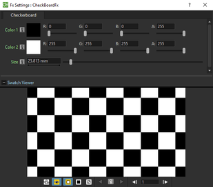
Creates a new column/layer containing a checkerboard defined by two Colors, and a grid Size.
توجه
The grid size can also be set by using a square gadget with a handle in the Viewer (see Using FX Gadgets ).
Color Card
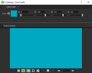
Creates a new column/layer containing the set Color. It can be used, for example, as a background color or to create a colorize effect by applying it combined with a multiply effect.
Kaleido
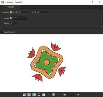
Repeats the Source generating a kaleidoscopic effect.
The center of the effect can be defined interactively, moving the small red cross widget in the preview area, or writing the desired values in the X and Y text fields.
The angle of reflection, and the number of iterations can be set in the appropriate input text fields (Angle and Count).
Tile
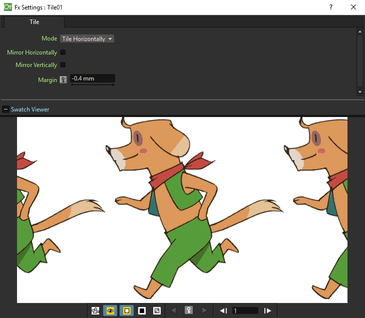
Repeats the Source content in order to define a larger image: the Tile mode forms a pattern that completely fills the camera shot, the Tile Horizontally repeats the source content horizontally; the Tile Vertically repeats the source content vertically.
The Mirror Horizontally and Mirror Vertically options repeat the tiles by flipping them respectively in the horizontal and vertical directions; If both the options are activated, tiles will be mirrored in both directions.
The Margin value sets the size of a margin around each tile, with positive values adding some space around the tiles, and negative values collapsing them.
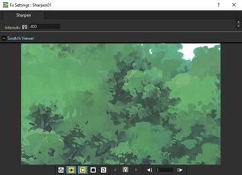
Blur
Blur
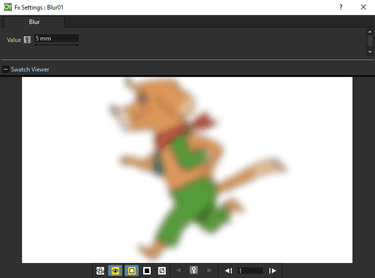
Softens the Source content, creating an out of focus effect, according to a specific Intensity.
Directional Blur
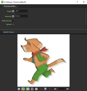
Blurs the Source content according to a specific Intensity along a specific direction defined by the Angle.
The Bidirectional option applies the blur also on the other side of the direction.
توجه
The intensity and the angle can also be set by using an arrow gadget with a handle in the Viewer (see Using FX Gadgets ).
توجه
The directional blur does not depend on the movement and the speed of the column to which it is applied.
Local Blur
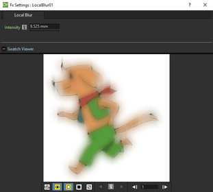
Blurs the Source content according to the brightness value of the node content connected to the Reference input handle. The Intensity value amplifies uniformly the blur given by the Reference node content.
Motion Blur
Creates a motion-blur effect, according to the movement of the Source content in the previous and current frame. The movement has to be defined by an animated column, pegbar or table: the higher the speed, the more visible the effect.
If the movement is constant between consecutive frames, you can increase or decrease the Intensity to have a more or less visible effect. If there is no movement between the previous and the current frame, no motion blur will be visible even though you may have set a high Intensity.
توجه
No result will be visible if the motion blur is applied to a column that always stands in the same position while the content is a level where the movement is drawn.
Radial Blur
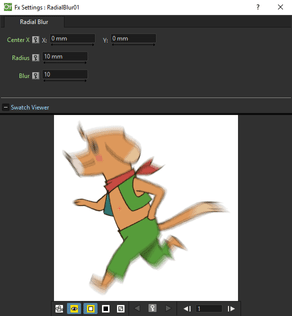
Blurs along radial lines whose origin is the set Center, defined by horizontal (X) and vertical (Y) coordinates, starting from an unaffected inner area defined by the Radius.
توجه
The center and the radius can be also set by using a point and a circle gadget with a handle in the Viewer (see Using FX Gadgets ); the center can be set in the FX Settings preview as well.
Spin Blur

Blurs along concentric circular lines as if the Source content turns around the set Center, defined by horizontal (X) and vertical (Y) coordinates, starting from an unaffected inner area defined by the Radius.
توجه
The center and the radius can be also set by using a point and a circle gadget with a handle in the Viewer (see Using FX Gadgets ); the center can be set in the FX Settings preview as well.
Distort
Free Distort
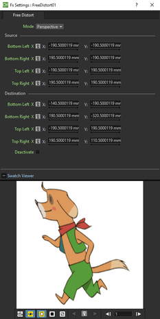
Distorts the Source content according to the position of four points, defined by horizontal (X) and vertical (Y) coordinates. For each point you can set the actual position and its origin, to determine which feature of the image will be distorted to the new position.
The Mode option menu lets you set the way the distortion is applied: Bilinear distorts the images according to the four points end positions, and Perspective forces the distortion to fit a perspective projection plane.
To better set the origin position for each point, you can use the Deactivate option that lets you see the image without distortion.
توجه
The position of the four points and their origins can be also set by using arrow gadgets with handles at the ends in the Viewer (see Using FX Gadgets ) and in the FX Settings preview as well.
Linear Wave
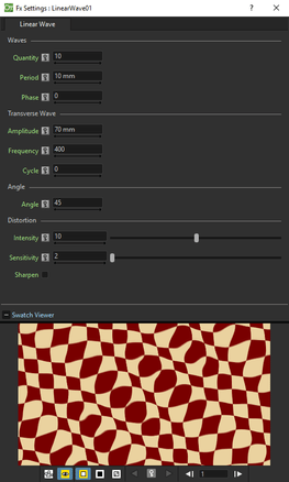
Distorts the Source content creating a wave effect that uses an automatically generated displacement map image. The Quantity value sets the number of waves; the Period sets the distance between waves; the Phase shifts distortion in the wave direction.
You can also add a Transverse Wave on the main linear waves: the Amplitude sets the intensity of the distortion; the Frequency sets the number of waves creating the distortion; the Cycle shifts the distorting waves.
A rotation for the whole wave effect can be set by using the Angle value.
The amount of distortion is controlled by the Intensity value; the detail of the distortion, by the Sensitivity parameter; the Sharpen option allows you to decrease the blur on the final result.
Perlin Noise
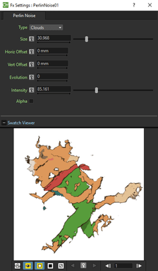
Distorts the Source content by using a computer-generated displacement map image whose type can be chosen between Clouds and Marble/Wood.
The amount of distortion is controlled by the Intensity value; the , by the Size of the displacement map grid. The Horizontal and Vertical Offset, and the Evolution stage of the displacement map image can be controlled as well; by setting the variation of these values between two keys, you can set how much the displacement map moves and changes during the animation.
The Alpha option adds also a transparency displacement to fully-opaque images.
توجه
The horizontal and vertical offset can also be set by using a point gadget in the Viewer (see Using FX Gadgets ).
Random Wave
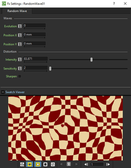
Distorts the Source content creating a random wave effect that uses an automatically generated displacement map image. It can be used, for instance, to create a reflection on a water surface, or an underwater view.
The stage of the displacement map image can be controlled by using the Evolution value; by setting the variation of this value between two keys, you set how much the displacement map image changes during the animation.
The position of the displacement map image can be shifted along the Horizontal and the Vertical axis. By setting the variation of this value between two keys, the distortion effect can be animated in any direction.
The amount of distortion is controlled by the Intensity value; the detail of the distortion, by the Sensitivity parameter; the Sharpen option allows you to decrease the blur on the final result.
توجه
The position along the horizontal and vertical axis can also be set by using a point gadget in the Viewer (see Using FX Gadgets ).
Ripple
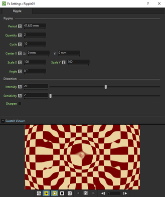
Distorts the Source content creating a circular wave effect that uses an automatically generated displacement map image. The Quantity value sets the number of ripples; the Period value sets the distance between ripples; the Cycle shifts the ripple distortion, with increasing values expanding the ripples, and decreasing values collapsing them.
The Center of the circular waves can be set with a Horizontal and Vertical value; circular waves can be scaled in the Horizontal and Vertical directions, and rotated according to a set Angle.
The amount of distortion is controlled by the Intensity value; the detail of the distortion, by the Sensitivity parameter; the Sharpen option allows you to decrease the blur on the final result.
توجه
The center and the period can be also set by using a point and a circle gadget with a handle in the Viewer (see Using FX Gadgets ); the center can be set in the FX Settings preview as well.
Warp
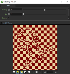
Distorts the Source content according to the brightness variation of the node content connected to the Warper input handle, that is used as a displacement map image affecting the Source content.
The amount of distortion is controlled by the Intensity value; the detail of the warp, by the Size of the displacement map grid; the Sharpen option allows you to decrease the blur on the final result.
Gradients
Diamond Gradient
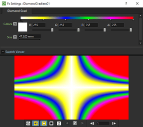
Creates a new column/layer containing a gradient, that goes hyperbolically from the center to the four corners, defined by a color spectrum (see Defining Colors and Color Spectrums ) and a Size value.
توجه
The size can also be set by using a circle gadget with a handle in the Viewer (see Using FX Gadgets ).
Four Points Gradient
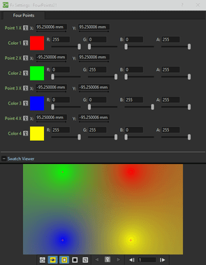
Creates a new column/layer containing a gradient defined by four Colors, defined by Red, Green, Blue and Alpha values, whose source Points can be placed where needed defining horizontal (X) and vertical (Y) coordinates.
توجه
The source points can also be set by using point gadgets in the Viewer (see Using FX Gadgets ) and in the FX Settings preview as well.
Linear Gradient
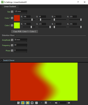
Creates a new column/layer containing a gradual blend between two Colors defined by Red, Green, Blue and Alpha values. The Size controls the area of the gradient between the two colors.
You can also add a Distortion Wave on the linear gradient: the Amplitude sets the intensity of the distortion; the Frequency sets the number of waves creating the distortion; the Phase shifts the distorting waves.
توجه
The size can also be set by using a gadget with two handles at the ends in the Viewer (see Using FX Gadgets ).
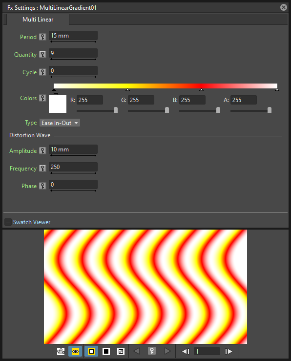
Multi Linear Gradient
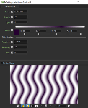
Creates a new column/layer containing a multi linear gradient defined by a color spectrum (see Defining Colors and Color Spectrums ). The Period value sets the size of a spectrum gradient; the Quantity is the number of times the spectrum is repeated; the Phase shifts the gradient colors.
You can also add a Wave distortion on the multi linear gradient: the Amplitude sets the intensity of the distortion; the Frequency sets the number of waves creating the distortion; the Phase shifts the distorting waves.
توجه
The period can also be set by using a gadget with two handles at the ends in the Viewer (see Using FX Gadgets )
Multi Radial Gradient
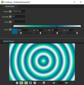
Creates a new column/layer containing a multi radial gradient defined by a color spectrum (see Defining Colors and Color Spectrums ). The Period value sets the size of a spectrum gradient; the Quantity is the number of times the spectrum is repeated; the Phase shifts the gradient colors.
توجه
The period can be also set by using a circle gadget with a handle in the Viewer (see Using FX Gadgets ).
Radial Gradient
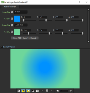
Creates a new column/layer containing a gradual blend between two colors, defined by Red, Green, Blue and Alpha values, shading them in a circular pattern. The Inner Size controls the area where the gradient between the two colors begins; the Outer Size where it ends.
توجه
The inner and outer sizes can be also set by using circle gadgets with a handle in the Viewer (see Using FX Gadgets ).
Spiral
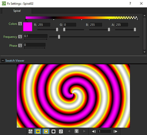
Creates a new column/layer containing a spiral pattern gradient defined by a color spectrum (see Defining Colors and Color Spectrums ). The Frequency sets the size and number of the spires; the Phase shifts the gradient colors.
Square Gradient
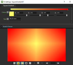
Creates a new column/layer containing a square gradient, that goes linearly from the center to the four corners, defined by a color spectrum (see Defining Colors and Color Spectrums ) and a Size value.
توجه
The size can also be set by using a rotated square gadget with handles in the Viewer (see Using FX Gadgets ).
Image Adjust
Adjust Levels
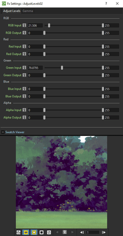
Adjusts the highlights and shadows of the Source content by remapping pixels intensity according to the Input and Output levels values for the RGB, Red, Green, Blue and Alpha channels; it also controls the Gamma value for each channel separately.
For each channel the Input values remaps pixel intensity whose value is equal or lower than the Minimum value, to 0, and those whose value is equal or higher than the Maximum value, to 255. This may be helpful to increase the contrast of an image.
For each channel the Output values remaps pixel intensity whose value is lower than the Minimum value, to the Minimum value, and those whose value is higher than the Maximum value, to the Maximum value. This may be helpful to decrease the contrast of an image.
Channel Mixer
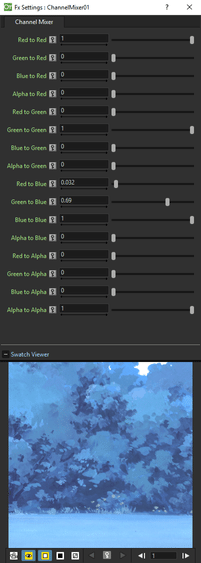
Swaps the channels of the Source content. For each channel you can set if it remains as it is, or if you want it to have another channel mixed. For example to leave the red channel as it is, Red to Red is 1, the other channels to Red are 0; by setting Green to Red to 0.5 adds half intensity of the green channel to the red one.
It can be used for example to create a black and white key for an image with the alpha channel, by setting all the values to 0 but the Alpha to Red, Green, Blue and Alpha to 1.
Curves
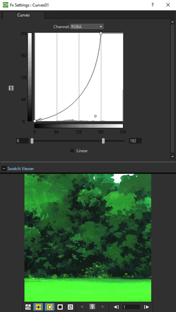
Adjusts the tonal range of the Source content by remapping pixels intensity according to a tonal curve for the RGB, Red, Green, Blue and Alpha channels.
The horizontal axis of the graph represents the original brightness levels of the pixels (Input levels); the vertical axis represents the new brightness levels (Output levels).
The default diagonal line indicates that no pixels are mapped to new values, so all pixels have the same Input and Output values.
It is possible to use many adjustment points to correct the curve: to add a point, click the curve; to change the curvature, use the point tangent handles; to delete a point, select it and use the delete shortcut (by default the Delete key).
The Linear option constrains the curve to a series of straight segments.
Despeckle
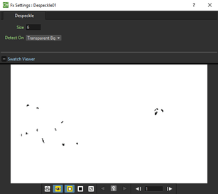
Elimantes small imperfections (dirt, scratches, stains and similar) of the drawing. The size in pixels of the details that will be retouched can be defined in the Size input text field. The background of the images can be Transparent or White, the choice is available in the Detect On menu.
In the preview area is possible to check the results to avoid erasing details relevant for the drawing.
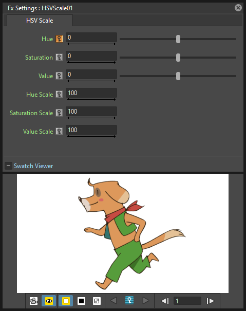
HSV Scale
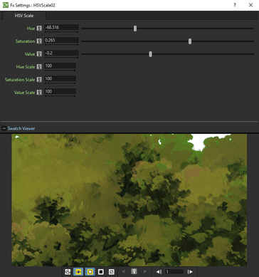
Shifts the Hue, Saturation and Value values of the Source content. Hue ranges from -180 to 180; Saturation and Value from -100 to 100. All the three settings preserve their original value at 0.
Invert
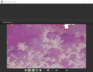
Inverts the color values of the Source content, e.g. makes a positive black and white image negative, or a positive one from a scanned black and white negative.
Multitone
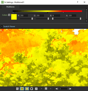
Applies to the Source content the colors defined by a color spectrum (see Defining Colors and Color Spectrums ) according to the image brightness. The original image is turned into black and white and the color on the far left of the spectrum will be use for black pixels, the color on the far right for white pixels, and in-between colors for in-between grey pixels.
RGBA Cut
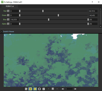
Delimits the Minimum and the Maximum values of the Red, Green, Blue and Alpha components of the Source content. The maximum can be decreased from 255, the original value, to 0, when no red, green, blue or alpha component will be visible. The minimum can be increased from 0, the original value, to 255, when the red, green, blue components will be saturated, and alpha will be fully opaque.
RGB Fade
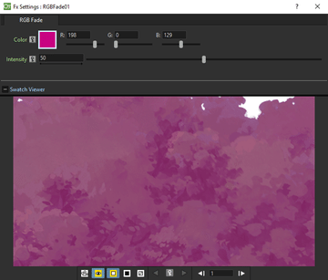
Fades the Source content toward a color defined by Red, Green and Blue values. The Intensity, expressed as a percentage, ranges from 0 (no fade) to 100 (fade to full color).
RGBA Scale
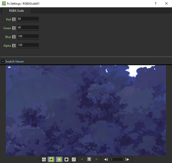
Changes the percentage of the Red, Green, Blue and Alpha components of the Source content. At 0 there is no red, green, blue or alpha component; at 100 the components have their original value.
Layer Blending
Add
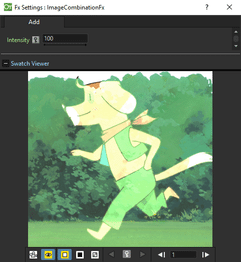
Adds the red, green and blue values of the Up node content to the Down one, pixel by pixel.
If no Down node is defined, the adding operation is applied to all the images underlaying the Up node content according to the Xsheet/Timeline layering order.
The Intensity value expresses the percentage of values used in the addition; a negative value defines a subtraction instead of an addition.
Color Burn
Darkens the pixel colors of the Down node content in order to reflect the color of the Up node content. The white in the Up node content does not affect the result.
If no Down node is defined, the color burning operation is applied to all the images underlaying the Up node content according to the Xsheet/Timeline layering order.
Color Dodge
Brightens the pixel colors of the Down node content in order to reflect the color of the Up node content. The black in the up node content does not affect the result.
If no Down node is defined, the color dodging operation is applied to all the images underlaying the Up node content according to the Xsheet/Timeline layering order.
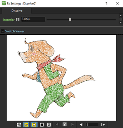
Cross Dissolve
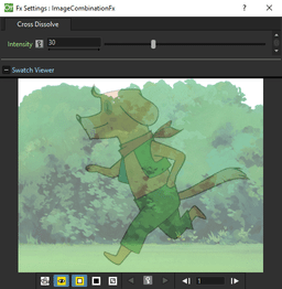
Creates a cross-dissolve between the Up and Down node content. When the Intensity value is 0, only the Down node content is visible; when it is 100, only the Up one.
Darken
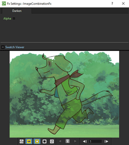
Compares the pixels color of the Up and Down node content and selects the darker one as the result color. The white in the Up node content does not affect the result; the black gives a black result.
If only one node is defined, the darkening operation is applied to all the images underlaying its content according to the Xsheet/Timeline layering order.
Lighten
Compares the pixels color of the Up and Down node content and selects the lighter one as the result color. The black in the Up node content does not affect the result; the white gives a white result.
If only one node is defined, the lightening operation is applied to all the images underlaying the connected node according to the Xsheet/Timeline layering order.
Local Transparency
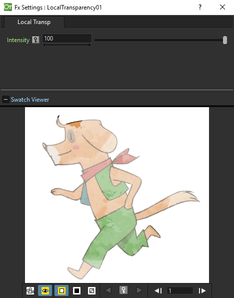
Applies a transparency to the Source content according to the brightness value of the node content connected to the Reference input port.
The Intensity value amplifies uniformly the transparency given by the Reference node content.
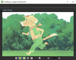
Multiply
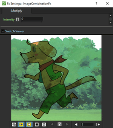
Multiplies the red, green, blue and alpha values of the connected noded content.
The Intensity value expresses the percentage of values used in the multiplication. By activating the Alpha option, also the alpha information is considered.
If only one node is defined, the multiplying operation is applied to all the images underlaying theupper node content according to the Xsheet/Timeline layering order.
Over
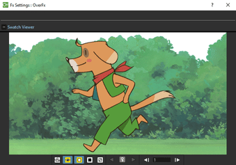
Puts the connected nodes one over the other. Each time a node is connected a new port will be added, this way the overlap of columns can be defined regardless from the Xsheet columns (or Timeline layers) order. The contents order is up to bottom, where the node connected on the upper port will be over the other ones. This can be used when you need to combine several nodes in a single one, for example to mask several columns with the same mask.
Premultiply
Premultiplies the alpha channel of the Source node content.
Full-color images which have a meaningful alpha channel come in two types: premultiplied or not. A non-premultiplied image can be recognized when it is loaded in OpenToonz because its edge, where there is a complete transparence on one side and opacity on the other, is not smooth, but displays a solid halo. With the premultiply effect it is possible to transform the image alpha-channel so that it is correctly read by OpenToonz.
توجه
Full-color images can also be premultiplied by using a Level Settings option, or processed permanently in the browser, so that there is no need to apply the effect in the schematic (see Editing Level Settings and Using the File Browser ).
Screen
Combines by multiplying the inverse of the pixels color of the Up and Down node content, giving a result color that is lighter than both Up and Down node pixels, except when one of them equals 0. The black in the Up node content does not affect the result; the white gives a white result.
If no Down node is defined, the screening operation is applied to all the images underlaying the Up node content according to the Xsheet/Timeline layering order.
Subtract
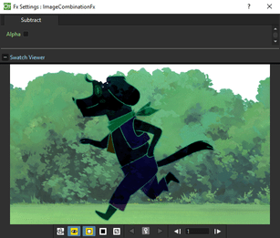
Subtracts the red, green and blue values of the Up node content from the Down one, pixel by pixel. By activating the Alpha option, also the alpha information is considered.
If only one node is defined, the subtraction operation is applied to all the images underlaying connected node content according to the Xsheet/Timeline layering order.
Transparency
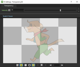
Sets the transparency of the Source content. The Intensity, expressed as a percentage, ranges from 0, fully opaque, to 100, fully transparent.
Light
Backlit
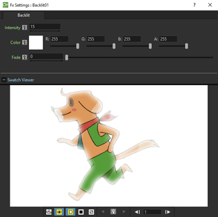
Creates a backlit effect, using the Light node content as a light source affecting the Source node content by the set Intensity. The light node content can be also faded to a Color defined by Red, Green and Blue values, according to the set Fade.
Body Highlight
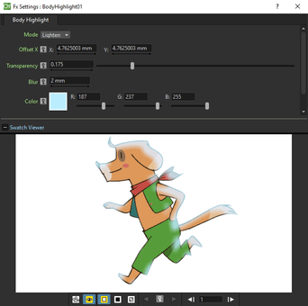
Creates a highlighted area for the Source node content, according to its alpha channel. You can set the Color of the highlight, as well as a Transparency and a Blur value to be applied.
The shifting of the highlighted area is defined by horizontal (X) and vertical (Y) Offset values, that can also be interactively set in the preview of the FX Settings window, where the offset center is displayed with a cross.
Enabling the Invert option the effected areas will be toggled.
The effect can be used to create a body shadow as well, by defining a black color for the highlight.
Cast Shadow
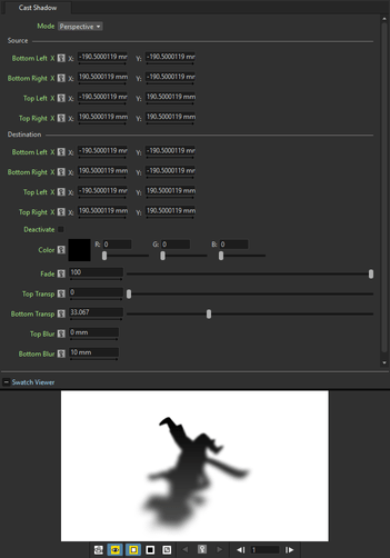
Turns the Source content into a shadow that can be distorted and faded to a color with a variable transparency and blur.
The distortion can be done like in the Free Distort effect (see Free Distort ). The fade Color can be defined by Red, Green and Blue values and a Fade intensity can be set. A different Blur and Transparency value can be set for the top and the bottom part of the Source content, in order to have a more realistic shadow.
Glow
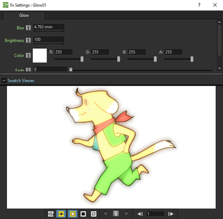
Creates a glowing effect, using the Light node content as a light glowing on the node content connected to the Source input port. The Blur and Brightness of the glowing can be set; the Light node content can be also faded to a color defined by Red, Green and Blue values, according to the set Intensity.
If no Source node is defined, the glowing is applied to all the images underlaying the Light node content according to the Xsheet/Timeline layering order.
Light Spot
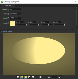
Creates a new column/layer containing a light spot whose size and color can be set respectively with the Width and Height values, and the Reg, Green, Blue and Alpha values. The Softness sets the light diffusion in the area outside the spot.
توجه
The width and height can be also set by using a box gadget with handles in the Viewer (see Using FX Gadgets ).
Raylit
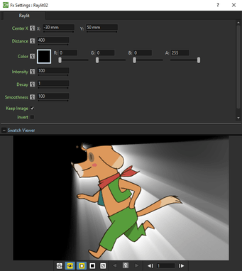
Places a source of light behind the Source node content, casting rays of light outside or inside the image outline.
The light source position is defined by horizontal (X) and vertical (Y) coordinates. By changing the light source position you change the way rays are cast along the image outline; by changing the Distance value you can make the light source approach to or go away from the image.
Properties of the light can be set by defining the Intensity, the Color, that is set by Red, Green, Blue and Alpha values, the Decay, that is the decrease of the light intensity according to its distance from the image, and the Smoothness, that determines how sharp the rays are along the image outline.
The Invert option switches the casting of rays of light from the outside of the image to the inside.
The Keep Image check-box determines if the original drawing is rendered in the output or not.
توجه
The center can be also set by using a point gadget in the Viewer (see Using FX Gadgets ) and in the FX Settings preview.
توجه
The Source node content needs to have a significant alpha channel in order to have an effective result.
Color Raylit
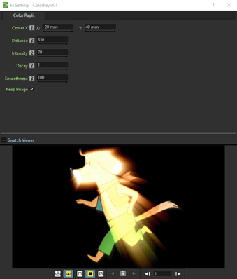
Places a source of light behind the Source node content, casting rays of light outside the image outline.
The light source position is defined by horizontal (X) and vertical (Y) coordinates. By changing the light source position you change the way rays are cast along the image outline; by changing the Distance value you can make the light source approach to or go away from the image.
The colours of the rays are calculated from the original drawing colours.
Properties of the light can be set by defining the Intensity, the Decay, that is the decrease of the light intensity according to its distance from the image, and the Smoothness, that determines how sharp the rays are along the image outline.
The Keep Image check-box determines if the original drawing is rendered in the output or not.
Target Spot
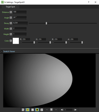
Creates a new column/layer containing a light spot whose size and color can be set respectively with the Width and Height values, and the Red, Green, Blue and Alpha values. The direction of the spot can be set by defining the Distance of the light from the table and the Angle between the light spot direction and the table. The Decay, that is the decrease of the light intensity according to the distance from table, can be controlled as well.
Matte
Erode/Dilate
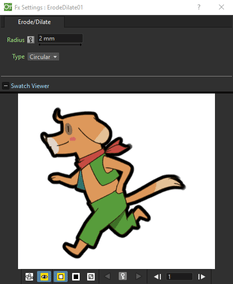
Morphologically erodes or dilates the alpha channel of the connected node by the specified value, where positive values correspond to dilations and negative ones to erosion.
The Type parameter defines the shape of the corners of the frame, applied around the image, when the Radius value is positive.
HSV Key
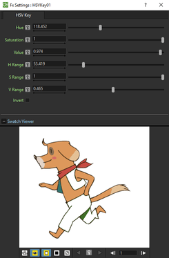
Defines a chroma key for the Source content using the set Hue, Saturation and Value values. You can set the range for each value by using the related Range slider. The selection can be inverted using the Invert button.
Matte In
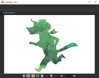
Makes the Source content visible only inside the opaque areas of the node content connected to the Matte input port.
Matte Out
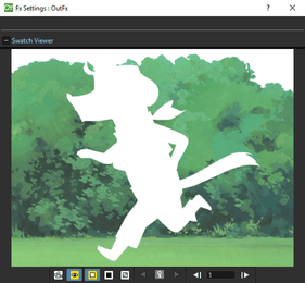
Makes the source content visible only outside the opaque areas of the node content connected to the Matte input port.
RGB Key
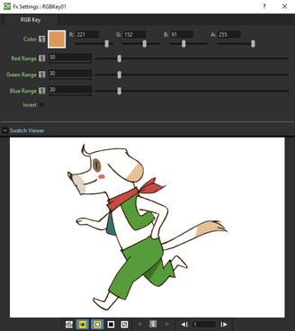
Defines a chroma key for the Source content using the set Red, Green and Blue values. You can set the range for each value by using the related Range slider. The selection can be inverted using the Invert button.
Visible Matte In
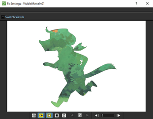
Makes the Up node content visible only inside the opaque areas of the node content connected to the Down input port, keeping the Down node still visible.
Noise
Noise
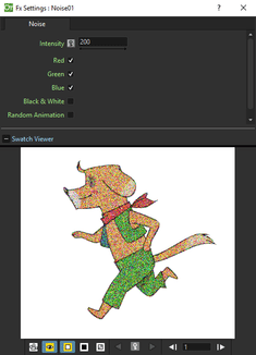
Adds a noise effect to the Source content according to the set Intensity. You can decide which noise component among Red, Green and Blue you want to activate, and if the result has to be in Black and White.
Salt & Pepper Noise
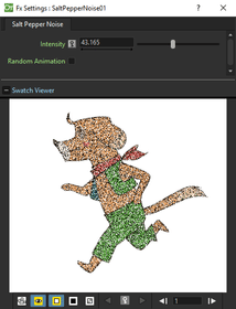
Adds a black and white noise effect to the Source content according to the set Intensity.
Render
Clouds
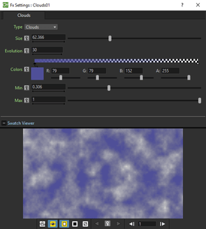
Creates a new column/layer containing a fractal image whose type can be chosen between Clouds and Marble/Wood. The Size affect the grid used for generating the fractal image; a color spectrum defines the used colors (see Defining Colors and Color Spectrums ).
Increasing the Minimum value shifts the color spectrum to the right, and consequently more pixels will be colored as the color defined at the far left of the spectrum. Decreasing the Maximum value shifts the color spectrum to the left, and consequently more pixels will be colored as the color defined at the far right of the spectrum.
The Evolution stage of the fractal image can be controlled as well; by setting the variation of this value between two keys, you set how much the fractal image changes during the animation.
Particles
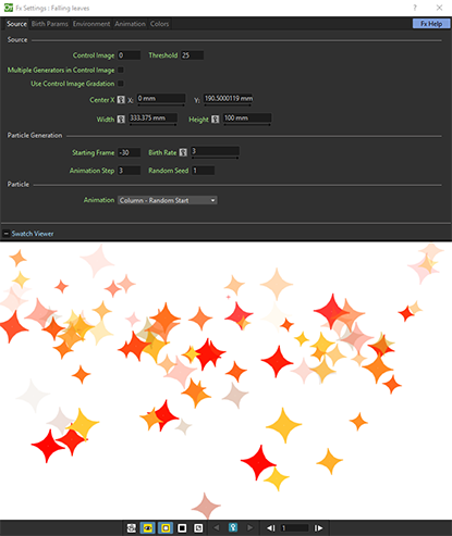
The Particles effect creates a new level in the selected column/layer containing particles.
It allows you to simulate a wide range of phenomena, such as rain, snow, sparkles, smoke, and a random configuration of elements, for example a field of shining stars starting from one shining star or the waving grass in a meadow starting from one animated blade of grass.
Text Iwa
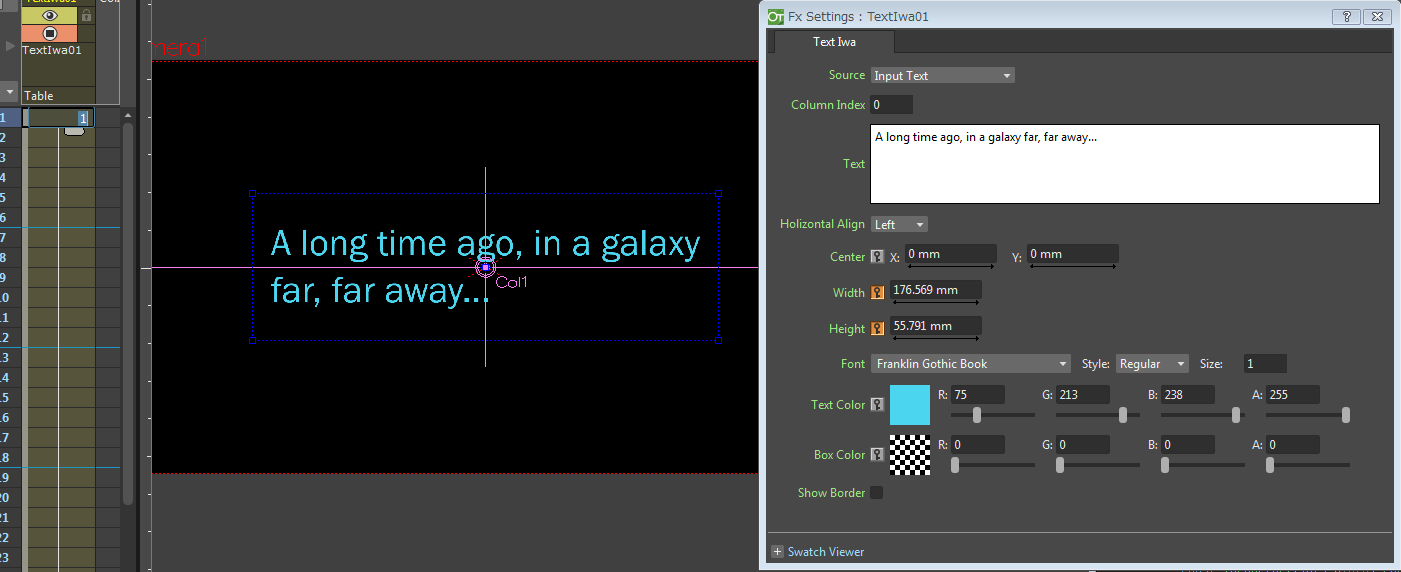
Creates a new column/layer containing editable and animatable text, using the following parameters:
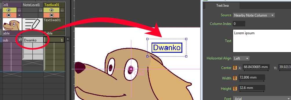
Source, specifies the text source. You can choose one from:
Nearby Note Column: Get the text from Note Level column put on the directly left side of the Text Iwa effect column, in the Xsheet (for Timeline view, the Note Level layer just under the effect layer is used). If the respective column/layer does not contain a Note Level or the cell is empty, text will not be rendered.
Specified Note Column: It's similar to the Nearby Note Column option, but the Note Level column number to use can be specified using the Column Index field below.
Input Text: The text typed in the Text field below will be used (as shown in the image on top).
Column Index, specifies the source Note Level column number to use. Only used in Specified Note Column Source mode.
Text, specifies the source text. Only used in Input Text Source mode.
Horizontal Align, specifies the text align. Options are: Left, Right, Center, and Justify.
Center X:, Y: specify the position of the text.
Width, Height, define the dimension of the text box. Just like in the Text items of the Clapperboard feature, the font size will be automatically adjusted in order to fit the box (see Using The Clapperboard ).
Font, specifies the font family to use.
Style:, specifies the font style to use.
Size:, specifies the maximum font size to use.
توجه
The Size value will only take effect if the automatically-calculated font size (in order to fit the specified text box) is bigger than the value specified for this parameter.
Text Color, specifies the color of the text. This color will also be used for the border line.
Box Color, specifies the background color of the text box.
Show Border, when activated, a border line will be rendered around the text bounding box. Please note that the text box (specified by the user) and the text bounding box (automatically computed from the rendered text) may become different, especially when the maximum font Size parameter is set to a small value.
توجه
Known Issue: When you are using a Note Level column for the source text, a change in the note text will not automatically trigger the preview regeneration. You will need to manually regenerate the preview using the context menu of the Viewer.
Stylize
Color Emboss
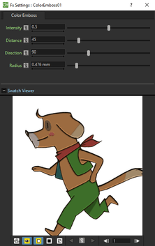
Traces the edges of the Source content with a combination of highlights and shadows. You can set the Intensity of the effect, and the Distance and Direction of the light that create the emboss effect. The Radius sets the depth of the embossing.
By connecting a node to the Controller port, the Source content will be embossed according to the Controller node content.
Emboss
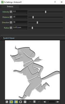
Turns the Source content to grey areas and traces its edges with a combination of highlights and shadows. You can set the Intensity of the effect, and the Distance and Direction of the light that create the emboss effect. The Radius sets the depth of the embossing.
Mosaic
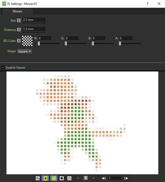
Turns the Source content in a series of tiles according to the specified Size and Distance. The color and transparency of the tiles are sampled from the source content.
A Background Color can be set, and will be visible around the tiles. The tile shape can be chosen between Square and Round.
Posterize
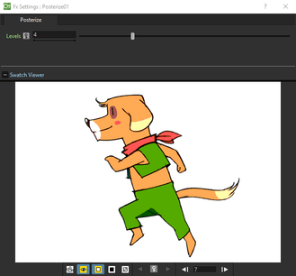
Converts the Source content into a number of shades according to the set number of Levels. The shades depends on the brightness values of the source content and the levels are intended for each channel; for example, two levels produces six colors: two for the red, two for the green, and two for the blue.
Solarize
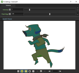
Blends a negative and a positive version of the Source content, as if exposing a photographic print briefly to light during development. You can set the Intensity of the effect and control the Peak Edge, that is the amount of positive and negative image that is used in the blend.
Toonz Level
Toonz Level type of effects can be applied only to Toonz Vector and Toonz Raster (PLI and TLV files). They usually affect the drawings they are applied to according to Style indexes. Style indexes can be retrieved in the Palette after the # symbol in the Style tooltip, or in the bottom right corner of the style in any of the Thumbnails View modes.
Index numbers can be specified in the related text field, separated by a comma. To define a range of indexes, you should type the first and last separated by a dash (e.g. 4-7 will refer to indexes 4, 5, 6 and 7). To select all indexes, type all ; to select no index, type none .
Toonz Level type of effects have to be always applied first when a series of effects are applied to an animation level, as they work only on Toonz Vector or Toonz Raster levels that have not been transformed by other type of effects. However two or more Toonz Level type of effects can be applied to the same animation level.
Art Contour
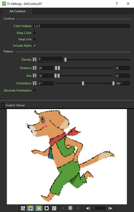
Creates in the Source content a pattern, by repeating the Controller node content, along lines painted with styles whose indexes are specified in the Color Indexes text field. It can be used for example to create scattered brush, or hair and fur effects along drawing lines.
The Keep Color option assigns the color of the line to the applied pattern; while the Keep Contour option retains the drawing line that will be visible beneath the pattern.
The way the contents of the Controller node create the pattern depends on the Pattern settings.
The Density sets the amount of pattern to be applied along the line. By setting the Density to 0, you can specify a Minimum and Maximum Distance between two subsequent images applied as pattern on the line.
The Size sets the Minimum and Maximum resizing percentage applied to the images used as the pattern; the value 100 is the original size of the images.
The Orientation sets the Minimum and Maximum rotation angle for the images used as the pattern, according to the line direction; the value 0 display the images perpendicular to the line direction. If the Absolute Orientation option is used, the orientation values do not depend on the direction of the lines: the value 0 is the original images orientation.
Calligraphic Line
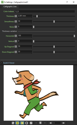
Changes in the Source content the thickness of the drawing lines painted with styles whose indexes are specified in the Color Indexes text field.
You can specify the Thickness increase and how it is applied, as a percentage, to the different line directions Horizontal, Vertical, Up Diagonal, Down Diagonal.
The Smoothness sets the smoothness of the passage between sections of the lines affected by the effect, and those not affected; while the Noise sets the regularity of the edge of the line.
Color Blending
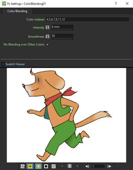
Blends in the Source content lines and areas painted with styles whose indexes are specified in the Color Indexes text field. It can be used for example to blend shadow and highlight areas with the plain colored area, or to create gradients of colors.
The Intensity sets how wide the blended area between the selected colors will be; while the Smoothness sets how smooth the dithering between blended colors is.
The No Blending over Other Colors option stops the blending as soon as a line, or an area, whose index is not included in the selection, is detected; if deactivated, the blending between selected colors continues under excluded lines and areas.
External Palette
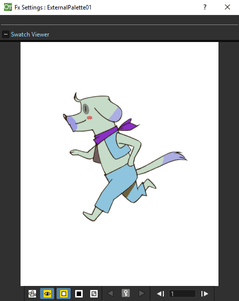
Applies to the Source content the palette node connected to the Palette input port; if a column node is connected to the Palette input port, the palette related to its content will be considered.
The original styles of the Toonz levels contained in the source node are replaced with those of the levels contained in the palette node according to their style indexes.
Outline
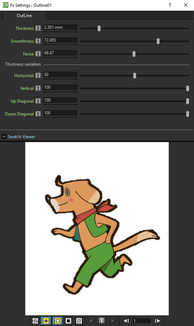
Changes in the Source content the thickness of the drawing external outline.
You can specify the Thickness increase and how it is applied, as a percentage, to the different line directions Horizontal, Vertical, Up Diagonal, Down Diagonal.
The Smoothness sets the smoothness of the passage between sections of the lines affected by the effect, and those not affected; while the Noise sets the regularity of the edge of the outline.
Palette Filter
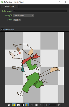
Filters the styles of the Source content palette according to the indexes specified in the Color Indexes text field.
The Apply To option menu lets you choose if you want to affect Lines & Area, only Lines or only Areas, even if painted with the same styles; the Action option menu lets you choose if you want to keep or remove the specified styles.
Pinned Texture
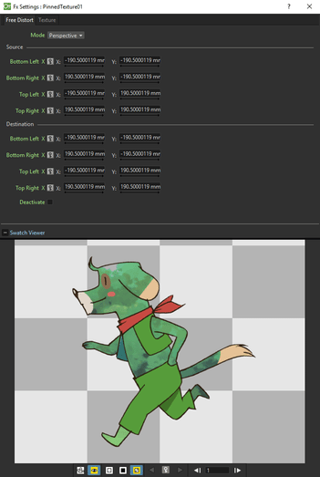

Distorts the Texture node content and applies it to the Source content areas that are painted with styles whose indexes are specified in the Color Indexes text field.
The distortion can be done like in the Free Distort effect (see Free Distort ) and the texture can be applied like in the Texture effect (see below).
Texture
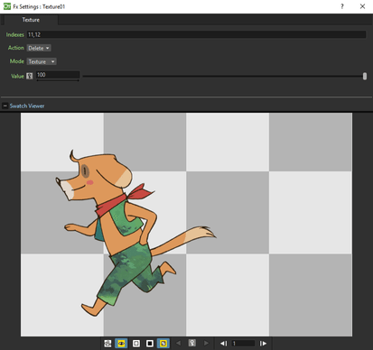
Applies the Texture node content to the Source content lines and areas that are painted with styles whose indexes are specified in the Color Indexes text field.
As the texture node content can be animated as you like, this effect allows you to generate animated texture as well.
The Action option menu lets you choose if you want to apply the texture to the specified styles (Keep) or to apply it to all styles except for the specified ones (Delete).
The Mode option menu lets you set how the texture node content will be applied: Texture uses the texture to replace selected styles; Pattern preserves the original colors but varies them according to the texture brightness; Add, Subtract, Multiply, Lighten and Darken defines the way the texture is applied to the original colors (see Layer Blending ). In case the Add, Subtract or Multiply mode are selected, you can also set the Value of the effect.
توجه
To repeat the texture image and tile it to create a larger texture, you can apply the Tile effect to the texture column before linking it to the Texture node (see Tile ).
Shaders
OpenToonz enables support for effects rendered through hardware-accelereted pixelshaders. Shaders are simple programs compiled by a graphics processing unit that harness the massively parallel architecture of modern graphics devices, to execute with extreme speed. OpenToonz's shader effects are written in the OpenGL Shading Language (GLSL), and are located in OpenToonz stuff/library/shaders. Refer to the readme.txt file there for further details on editing or creating new shader effects.
Caustic
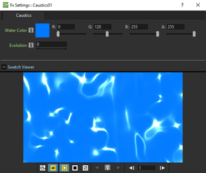
Creates a new column/layer containing a simulation of the reflection of light on a water surface. Sets the color of the water defining the RGBA values of the Water Color parameter.
The stage of the displacement map image can be controlled by using the Evolution value; by setting the variation of this value between two keys, you set how much the displacement map image changes during the animation.
Fireball
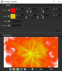
Creates a new column/layer containing a ball of flames erupting from a point.
A range of colors can be defined setting the RGBA values of color 1 and color 2. The stage of the displacement map image can be controlled by using the Evolution value; by setting the variation of this value between two keys, you set how much the displacement map image changes during the animation.
Glitter
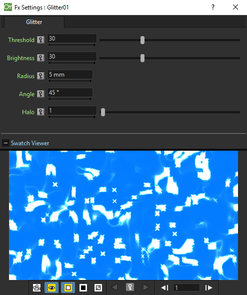
Adds cross-shaped light rays extending from the brightest part of an image.
Use Threshold to specify the cut-out on the input image's brightest part. Higher values will make the fx add lights also to darker image parts, producing more lights. The Brightness specifies the brightness of added light rays; the Radius specify how much the light rays will extend from bright input pixels; the Angle specify the angle of light crosses. A value 0 means that produced light crosses will be axis-aligned. Halo is the amount of light disperion orthogonal to the direction of light rays. Higher values will produce broader rays.
Star Sky
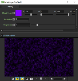
Creates a new column/layer containing a simple star field with variable brightness with overlayed clouds. Sets the color of the overlayed clouds defining the RGBA values of the Cloud Color parameter.
The stage of the stars displacement can be controlled by using the Evolution value; by setting the variation of this value between two keys, you set how much the displacement map image changes during the animation.
Use the Brightness parameters to define the brightness of the stars.
Sun Flare
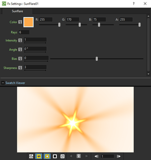
Creates a new column/layer containing rays of colored light extending from a radial gradient at the center. Sets the color of the sun rays defining the RGBA values of the Color parameter. The number of rays is defined by the Rays parameter while their brightness is set by the Intensity one. The angle parameter sets the direction of the rays and the Bias parameter define the size of the rays. Use the Sharpness parameter to make the rays sharper or smoother.
Wavy
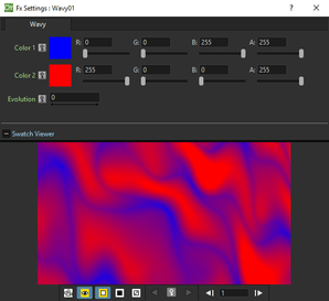
Creates a new column/layer containing a simple gradient with a colored 'wavy' pattern. The waves colors are definied by setting the RGBA values of the Color 1 and Color 2 parameters. The stage of the displacement map image can be controlled by using the Evolution value; by setting the variation of this value between two keys, you set how much the displacement map image changes during the animation.
GPU Radial Blur
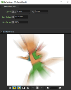
Blurs along radial lines whose origin is the set Center, defined by horizontal (X) and vertical (Y) coordinates, starting from an unaffected inner area defined by the Safe Radius. The Blur Factor parameter sets the amount of blur.
GPU Spin Blur
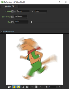
Blurs along concentric circular lines as if the Source content turns around the set Center, defined by horizontal (X) and vertical (Y) coordinates, starting from an unaffected inner area defined by the Safe Radius. The Blur parameter sets the amount of blur.