Using the Particles Effect
The Particles effect creates a new level in the selected column/layer containing particles.
It allows you to simulate a wide range of phenomena, such as rain, snow, sparkles, smoke, and a random configuration of elements, for example a field of shining stars starting from one shining star or the waving grass in a meadow starting from one animated blade of grass.
Using a wide variety of parameters available, the Particles effect can be completely customized. A series of Presets, simulating some basic events, are also available. You can look at these Presets to better understand how to set the parameters; or you can use them as the starting point to create your own effects.
Particles are defined by parameters organized in different folders: Source, Birth Params, Environment, Animation and Colors.
Примечание
Particles effect may have unexpected results when the Stretch option in Output Settings is used to set a higher FPS value, as this effect requires the original timing information (see Choosing the Output Settings ).
Defining Particle Images
Any column/layer content can be used as a particle: its animated content and its animation will be reflected by the particle animation, using the transformations and the drawings exposed in the column/layer cells at the related frame in each point of the particle life.
For example if a level is exposed in the column/layer at step two, the particle Texture will be animated at step two as well; or if you have a drawing that’s spinning because the column/layer is animated, the particle will be spinning as well.
To use a column/layer content as a particle, the column/layer node has to be linked to the Texture port of the particles effect node. As soon as a column/layer is linked to the texture input port, a new texture port is available: in this way it is possible to use the content of several columns/layers as particles.
Примечание
Image formats containing DPI information are loaded using that image DPI; in this case the particles level will be camera resolution independent.
Defining Control Images
A column/layer contents can also be used to control some parameters of the particles effect: its animated content and its animation will affect the particles parameter according to specific image properties, such as brightness or transparency.
For example if the level exposed in the column/layer is animated, and the column/layer is used to control the particles Source, the particles Source will follow the animation of the level; or if the column/layer is moving and it’s used to control the Gravity field, the Gravity field will move as well.
To use a column/layer contents as a Control Image, connect the column/layer node to a Control input port of the Particles effect node. As soon as the column/layer is linked to the Control input port, a new Control port is available: in this way it’s possible to use the contents of several columns/layers to control the Particles effect.
To apply the control image to a parameter, use the related field available in the FX Settings pane: to specify a Control Image, type the number related to the control image port; to use no control image, type the number 0.
Примечание
When the control images brightness is used to affect a particles parameter, transparent areas are considered as being completely black.
Source
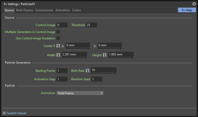
The particles Source is the area where the particles are generated. It can be defined in the Source page, by specifying its size and position, or a control image. The way particles are generated, for example their birth rate, can be controlled as well.
Source
Control Image
Sets if and which control image has to be used for the particles source (see Defining Control Images).
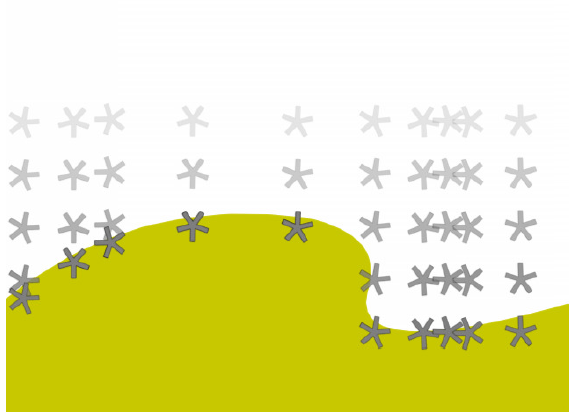
If used, particles are generated only inside the opaque areas of the Control Image.
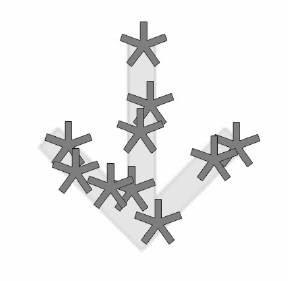
Particles generated according to an image-controlled source.
Threshold
This value defines which pixels of the Control Image are to be used for placing the paricles, defining a range based on the opacity value of its pixels. Lower the value and more opaque the pixels have to be for being used as particles generators.
Multiple Generators in Control Image
When activated, each defined opaque area of the Control Image will have the same number of generated particles, totalling the Birth Rate. For example if the Birth Rate is 20, and the Control Image has 4 defined opaque areas, 5 particles will be generated in each area.
Use Control Image Gradation
When activated, the intensity of the opacity in the Control Image defines the generation density of the particles. This option cannot be used at the same time as Multiple Generators in Control Image.
Center
Sets the source Center position, defined by horizontal (X) and vertical (Y) coordinates; it can also be interactively set in the preview of the FX Settings pane, where the Center point is displayed as a cross.
If you want to animate the Source to create a trail of particles, you can do it either by animating the Center coordinates, or by animating a column/layer, containing the source area, that has to be used as the Control Image for the Source (see above).
Примечание
The Center can be also set by using a point gadget in the viewer (see Using FX Gadgets ).
Примечание
The Center is not considered in case a Control Image is used.
Width and Height
Sets the size of the Source area.
Примечание
The Width and Height can be also set by using a box gadget with handles in the viewer (see Using FX Gadgets ).
Примечание
These values are not considered in case a Control Image is used.
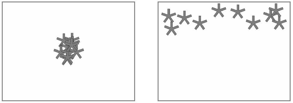
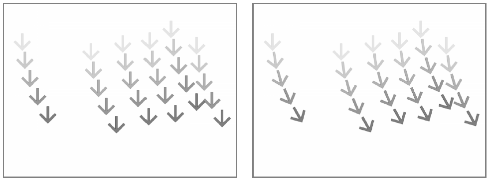
Particles generated according to a small square source at the center of the camera, and according to a wide box placed at the top of the camera.
Particle Generation
Starting Frame
Sets the frame at which the particles generation starts.
When you need a particles event to start before frame 1, you can set a negative Starting Frame value. For example if you need at frame 1 a snowfall, you cannot make the event start at frame 1, otherwise you will see only the first generated snowflakes; in this case you can set a negative value, for example -20, so that the snowfall has already evolved for 20 frames before being displayed at frame 1.
As the Starting Frame is an effect parameter, moving the Particles effect level up or down in the Xsheet (or left or right in the Timeline) will not change the actual starting frame: the parameter itself has to be edited.
Примечание
If the Starting Frame is higher than the first frame where a Birth Rate is set, the former value is used as the starting point of the event. For example if the Starting Frame is 20 and first frame with a positive Birth Rate is frame 15, from frame 15 to 20 no particles will be generated.
Birth Rate
Sets the number of particles to be generated in each frame. When the value is constant, in each frame the same number of particles will be generated. For example if the Birth Rate at frame 1 is 20, the first frame will contain 20 particles, the second 40, the third 60, and so on.
The Birth Rate value considers also decimal numbers. For example, if you set the birth rate to 0.2, a particle each five frames will be generated (0.2 multiplied by 5 is equal to 1 particle).
By animating the Birth Rate, you can control the quantity of particles in the effect. For example if you want only 20 particles starting from frame 1, you need to set a key at frame 1 with the Birth Rate set to 20, and another key at frame 2 with the Birth Rate set to 0.
Animation Step
Sets the step of the whole particles animation. This allows you to match the animation of the particle effect with the animation in the scene, in case the scene uses an animation step different from 1.
Random Seed
Creates a different particles configuration. With the same parameters values and the same Random Seed the particles configuration is always the same; changing the Random Seed allows you to retain all the set parameters but to change the particles configuration. Only integer numbers are considered.
Particle
Animation
The particle animation follows the source node content, but you can decide how that content is used, especially in case the Particles effect is longer than the Texture columns/layers content. The following options are available:
- Hold Frame randomly assigns a frame from the Texture node content to each generated particle; that frame is kept throughout the life of the particle.
- Random Frame randomly assigns a frame from the Texture node content to each generated particle, changing it randomly at each frame of the particle lifetime.
- Column assigns the first frame from the Texture node content to each particle when it is generated; the animation cycles following the Texture node content order throughout the life of the particle.
- Column - Random Start randomly assigns a frame from the Texture node content to each particle when it is generated; the animation cycles following the Texture content order throughout the life of the particle starting from the assigned frame.
- Column Swing - Random Start randomly assigns a frame from the Texture node content to each particle when it is generated; the animation moves from the assigned frame to the last or to the first, then keeps on swinging back and forth along the frames sequence, throughout the life of the particle.
Birth Parameters
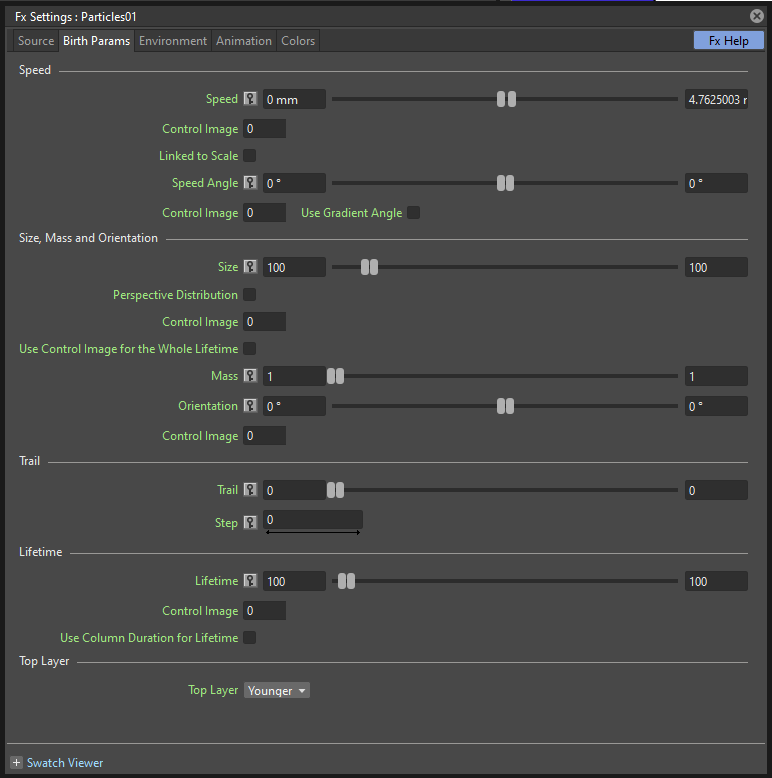
Each particle, when generated at the current frame, has some parameters that are assigned and retained throughout its life. Those attributes can be set in the Birth Params page.
Speed
Assigns a speed and a direction for each generated particle.
Speed
Assigns randomly a speed to each particle, according to the minimum and maximum values.
The speed value makes the particle move constantly as frames increase, and is expressed in the chosen unit of measure per frame. A negative value makes the particle move in the opposite direction of the one set by the angle.
Control Image
Sets if and which control image has to be used to control the particles speed (see Defining Control Images ).
If used, the speed value range defined above will be distributed according to the brightness value of the control image pixel where the particle is generated: particles will be faster where the image is brighter.
Linked to Scale
Assigns to each particle a speed value, taken between the minimum and maximum speed, according to the Size value applied to the particle. This causes the largest particles to be the fastest, emphasizing a depth of field effect.
Speed Angle
Assigns randomly to each particle an angle value defining the speed direction, according to the minimum and maximum values.
The value 0 is for an upward direction; higher values turn the direction clockwise.
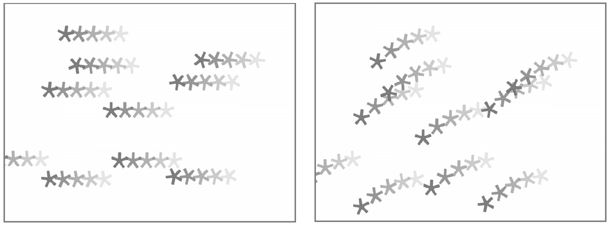
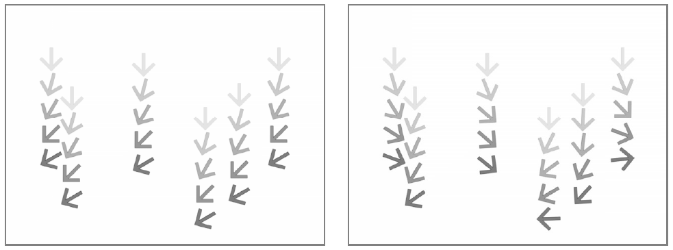
A particle animation with different random speed, and with different random speed and direction angle.
Use Gradient Angle
When activated, adjusts the initial velocity to the gradient vector of the Control Image Speed Angle.
Size, Mass and Orientation
Size
Assigns randomly a size to each particle, according to the minimum and maximum values. The size is expressed as a percentage, where 100 is the original size.
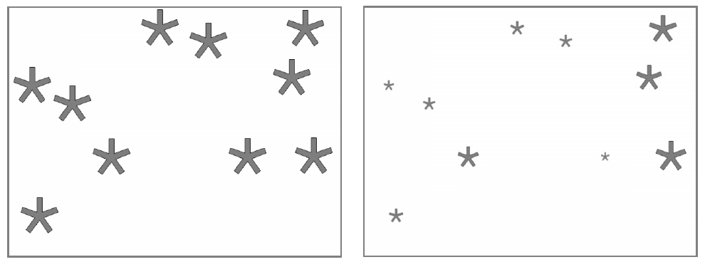
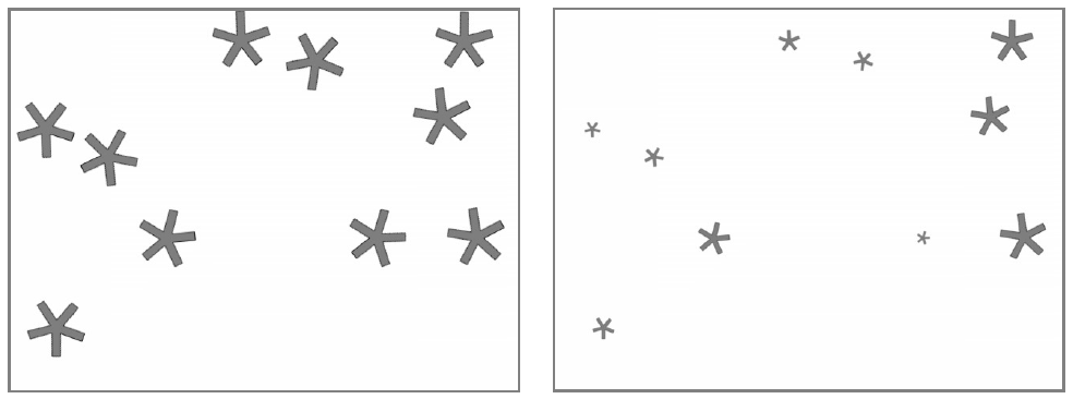
Particles generated with a fixed size and with a random one.
Perspective Distribution
When activated, and if a Control Image for Size is conected, particles size will be inversely proportional to their density. It can be used for placement of depth particles, as in a sea waves level. When this option is active, the Use Control Image Gradation option will be ignored.
Control Image
Sets if and which control image has to be used to control particles size (see Defining Control Images ).
If used, the size value range defined above will be distributed according to the brightness value of the control image pixel where the particle is generated: particles will be larger where the image is brighter.
Use Control Image for the Whole Lifetime
If activated, the defined control image is used to set the particles size for each frame of the particles life, ignoring any Size Increase value.
If deactivated the control image is used only at the birth of the particles, and any size variation depends only on the Size Increase value (see Size Increase ).
Mass
Assigns randomly a mass to each particle, according to the minimum and maximum values. The mass is taken into account when gravity affects the particles behavior.
Orientation
Assigns randomly an orientation to each particle, according to the minimum and maximum angle values.
The value 0 leaves the image as is; increasing values turn the particle clockwise.
Control Image
Sets if and which control image has to be used to control particles orientation (see Defining Control Images ).
If used, the orientation value range defined above will be distributed according to the brightness value of the control image pixel where the particle is generated.
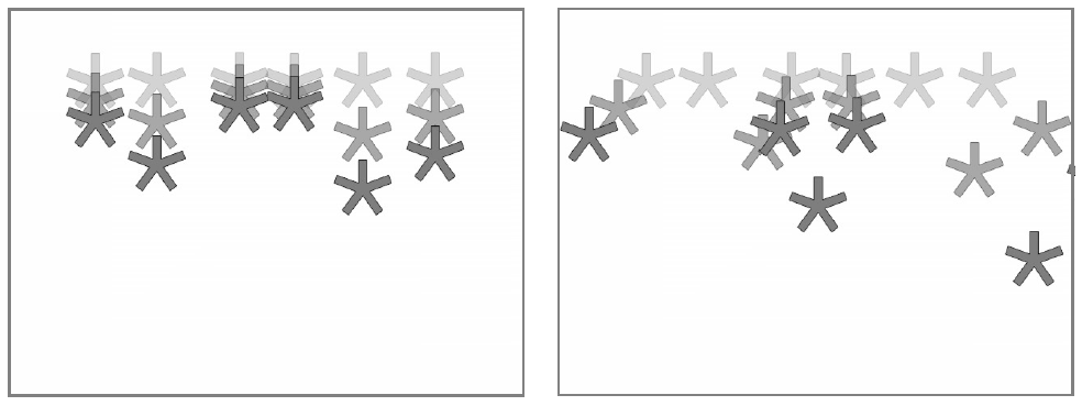
Different random orientation assigned to same-size and to different-sized particles.
Trail
Trail
Allows you to define a trail according to the particle motion by specifying how many previous frames positions have to be used to generate the trail. The number of frames the trail lasts is randomly assigned according to the minimum and maximum values.
Step
Sets how many particles will be visible in the trail. For example, if the trail value is 10 and the step is set to 2, the trail will be 10 frames long, but only five particles, one every two frames, will be visible.
Lifetime
Lifetime
Assigns randomly a lifetime to each particle, according to the minimum and maximum values. The lifetime is the number of frames the particle will last before disappearing.
For example if a particle is generated at frame 15 with an assigned lifetime value of 20, it will last till frame 35, disappearing at frame 36.
Control Image
Sets if and which control image has to be used to control particles lifetime (see Defining Control Images ).
If used, the lifetime value range defined above will be distributed according to the brightness value of the control image pixel where the particle is generated: particles will live longer where the image is brighter.
Top Layer
Top Layer
Defines the layering order of the generated particles. Options are the following:
- Younger places the latest generated particles on top of all the others.
- Older places the latest generated particles behind the previously generated ones.
- Smaller places smaller particles on top of the bigger ones.
- Bigger places bigger particles on top of the smaller ones.
- Random places each particle randomly in-between the previously generated particles.
Environment
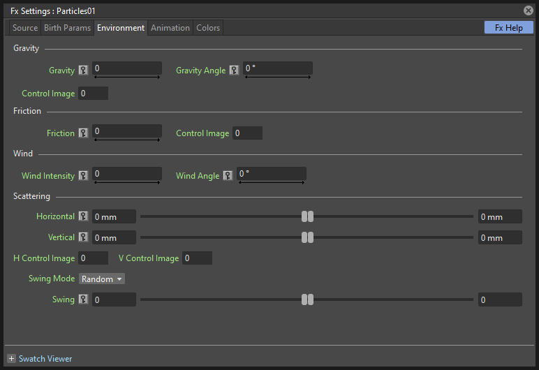
Particles behavior defined by their birth parameters can be affected by external events, such as gravity and wind, that can be defined in the Environment page.
Gravity
Simulates a single direction force that accelerates the particles, as gravity does.
Gravity
Sets the acceleration of gravity acting upon the particles: the motion generated by the intensity of the gravity increases as frames increase.
A negative value makes the particle accelerate in the opposite direction of the one set by the angle.
Gravity Angle
Defines the gravity direction. The value 0 is for a downward direction; higher values turn the direction clockwise.
A particle animation without and with gravity.
Control Image
Sets if and which control image has to be used to define a gravity field affecting the particles motion (see Defining Control Images ).
If used, the particles will be attracted by the brighter areas of the image, ignoring the set Gravity Angle value: the brightest areas of the image will have the Gravity value you set. For best results, the dark and light areas should be smoothly blended.
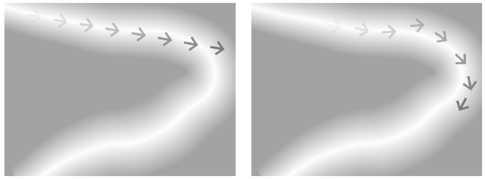
A single particle movement without and with an image-controlled gravity.
Friction
Friction
Simulates a force which has a direction opposite to the motion of the particles, in order to slow them down, or to stop them.
A negative value makes the particles accelerate in the direction of their own motion.
Control Image
Sets if and which control image has to be used to define a friction field affecting the particles speed (see Defining Control Images ).
If used, the particles motion will be affected by the brighter areas of the image: the brightest areas of the image will have the Friction value you set. For best results, the dark and light areas should be smoothly blended. If you want the particles to stop suddenly, use a high intensity value.
A particle animation with an image-controlled friction.
Wind
Simulates a speed that is added to the particles speed. The speed is constant, this means that there is no acceleration in the motion of the particles.
Wind Intensity
Sets the wind speed. A negative value makes the particle move in the opposite direction of the one set by the angle.
Wind Angle
Sets the angle value defining the wind speed direction.The value 0 is for an upward direction; higher values turn the direction clockwise.
For example if a particle is standing still, and at frame 10 a wind starts with an intensity of 50 and an angle of 90, the particle will move constantly rightward at each frame.
Scattering
Sets a random horizontal and vertical displacement that is added to the movement of the particles.
Horizontal
Sets the minimum and maximum displacement that can be generated and randomly added to the horizontal component of the particle movement. Positive values shifts the particle to the right; negative ones to the left.
Vertical
Sets the minimum and maximum displacement that can be generated and randomly added to the vertical component of the particle movement. Positive values shifts the particle to the top; negative ones to the bottom.
H Control Image
Sets if and which control image has to be used to control the horizontal scattering value (see Defining Control Images ).
If used, the horizontal scattering value range defined above will be distributed according to the brightness value of the control image: the horizontal scattering will be higher where the image is brighter.
V Control Image
Sets if and which control image has to be used to control the vertical scattering value (see Defining Control Images ).
If used, the vertical scattering value range defined above will be distributed according to the brightness value of the control image: the vertical scattering will be higher where the image is brighter.
Swing Mode
Sets the way the scattering values are used; options are the following:
- Random adds the horizontal and vertical scattering values to the particle movement at each frame.
- Smooth reaches the horizontal and vertical scattering values by interpolating values, in order to create a smooth movement. The interpolation lasts as many frames as set by the swing value set below; when the scattering values are reached, new values for each parameter are generated.
Swing
Sets the minimum and maximum number of frames throughout which the horizontal and vertical scattering values will vary, while remaining either positive or negative. This allows you to set a swinging movement where each swing lasts a random number of frames, still having a random scattering at each frame.
For example with a horizontal scattering between 1 and 8, and a Swing value with the minimum and maximum set to 10, the particle will be shifted with a random value of between 1 and 8 to the right for 10 frames; then at frame 11 the scattering changes, so that the random value between 1 and 8 will shift the particle to the left for the following 10 frames.
Animation
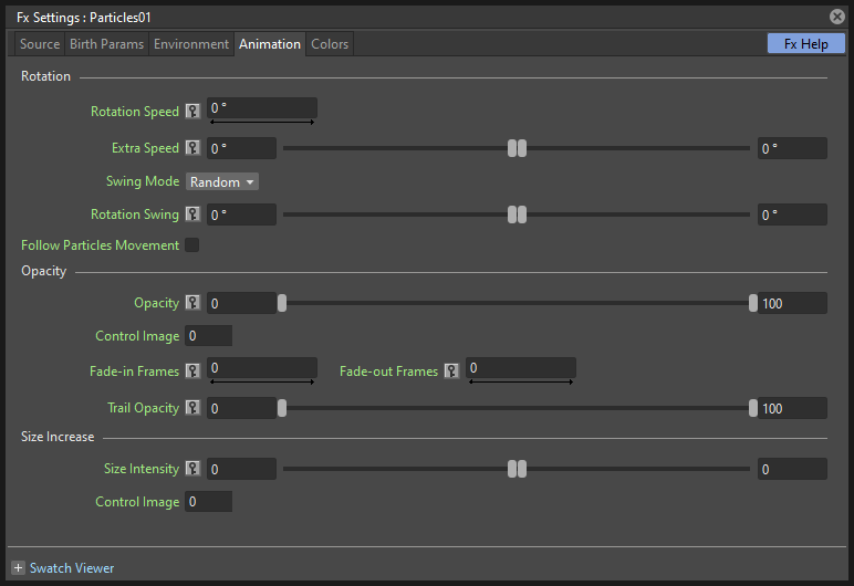
Particles birth properties can be transformed during their lifetime, for example particles can rotate, or change size, by using additional settings available in the Animation page.
Rotation
Controls the way each particle rotates around its center throughout its life.
Rotation Speed
Makes the particles rotate constantly as frames increase, and is expressed in degree per frame. Positive values makes the particle spin clockwise.
Unlike the directional Speed parameter, this parameter is not a birth attribute. This means that if in a 20 frames animation you animate the Rotation Speed value from -30 to 30, during the animation all the particles will rotate together, counterclockwise for the first 10 frames, then clockwise for the next 10 frames.
Extra Speed
Sets the minimum and maximum value that is randomly added to the rotational speed, thus creating a more chaotic rotation.
A particle animation with a fixed rotation speed, and with extra speed including smooth swing.
Swing Mode
Sets the way the spinning is performed; options are the following:
- Random, adds the extra speed values to the rotation of the particles at each frame.
- Smooth, reaches the rotational extra speed value by interpolating values, in order to create a smooth movement. The interpolation lasts as many frames as set by the swing value; when the extra speed value is reached, new values for each parameter are generated.
Rotation Swing
Sets the minimum and maximum number of frames throughout which the extra speed values will vary, while remaining either positive or negative. This allows you to set a swinging movement where each swing lasts a random number of frames, having a random extra speed at each frame.
Follow Particles Movement
Rotates the particles according to their movement direction. The particle preserves its original orientation when the movement is horizontal to the right.
A particle animation without and with the Follow Particles Movement option.
Opacity
Sets a fade-in process at the beginning of particles life, and a fade-out process at the end, according to the set minimum and maximum opacity values.
Opacity
Sets the minimum and maximum opacity values for the fade-in and fade-out processes. Values are expressed as a percentage, where 100 is the original opacity.
The fade-in process begins from the minimum value and reaches the maximum value at the end; the fade-out process begins from the maximum value and reaches the minimum value at the end.
Fade-in Frames
Sets the number of frames the fade-in process lasts, starting from the first frame of the particle life.
Fade-out Frames
Sets the number of frames the fade-out process lasts, starting from the last frame of the particle life and counting backward.
Size Increase
Size Intensity
Sets the minimum and maximum scaling factor to be applied to the particle in each frame. Positive values are for increasing the size of the particles, negative ones for decreasing it. Values are expressed as a percentage.
Control Image
Sets if and which control image has to be used to control particles size increase (see Defining Control Images ).
If used, the size increase value range defined above will be distributed according to the brightness value of the control image: particles will increase in size faster where the image is brighter.
Colors
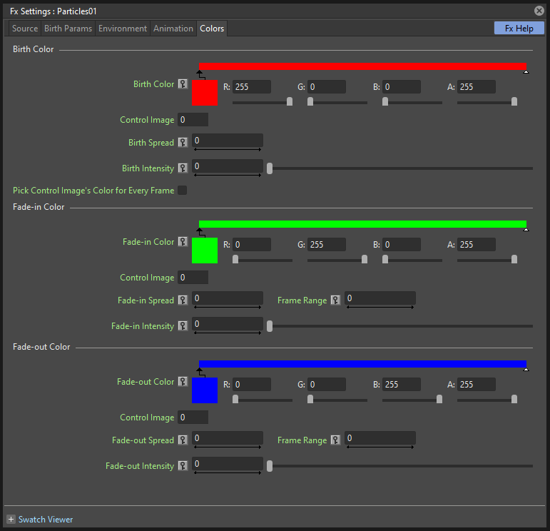
Particles can fade to specific colors at their birth, during their life and just before their death, by specifying settings in the Color page. The color parameters are birth attributes, i.e. they are assigned to the particles when they are generated.
Birth Color
Birth Color
Sets the range of colors to which particles fade at their birth, by defining a color spectrum (see Defining Colors and Color Spectrums ).
Control Image
Sets if and which control image has to be used to define the particles birth colors (see Defining Control Images ).
If used, particles will pick their birth color from the control image pixels according to their birth position.
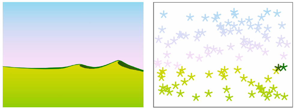
A control image used to assign color to the generated particles.
Birth Spread
Sets a spread value that will be added to the red, green and blue values of the color to which particles fade at their birth.
In this way particles will fade to a range of colors spreading from the colors defined in the spectrum or in the control image.
Birth Intensity
Sets the intensity of the birth color-fading.
Pick Control Image’s Color for Every Frame
When activated, at every frame the Control Image pixels will be sampled in the current position of the particles, changing their color.
Fade-in Color
Fade-in Color
Sets the range of colors to which particles fade at a certain number of frames after their birth, by defining a color spectrum (see Defining Colors and Color Spectrums ).
Control Image
Sets if and which control image has to be used to define the particles fade-in colors (see Defining Control Images ).
If used, particles will pick their fade-in color from the control image pixels according to their position.
Fade-in Spread
Sets a spread value that will be added to the red, green and blue values of the color to which particles fade in.
In this way particles will fade to a range of colors spreading from the colors defined in the spectrum or in the control image.
Frame Range
Sets the number of frames the fade-in process lasts, starting from the first frame of the particle life.
Fade-in Intensity
Sets the intensity of the fade-in process.
Fade-out Color
Fade-out Color
Sets the range of colors to which particles fade starting from a certain number of frames before their death, by defining a color spectrum (see Defining Colors and Color Spectrums ).
Control Image
Sets if and which control image has to be used to define the particles fade-out colors (see Defining Control Images ).
If used, particles will pick their fade-out color from the control image pixels according to their position.
Fade-out Spread
Sets a spread value that will be added to the red, green and blue values of the color to which particles fade out.
In this way particles will fade to a range of colors spreading from the colors defined in the spectrum or in the control image.
Frame Range
Sets the number of frames the fade-out process lasts, starting from the last frame of the particle life and counting backward.
Fade-out Intensity
Sets the intensity of the fade-out process.